NORD Drivesystems BU0180 User Manual
Page 150
SK 180E Manual for frequency inverters
150
Pre-series version
BU 0180 GB-0914
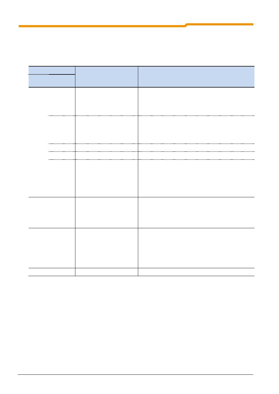
7.4 Table of possible reasons for the operating status "switch-on disabled"
The following table summarises the messages which are generated if the frequency inverter cannot be
enabled, although no fault is present.
Display
Reason:
Text in the ParameterBox
Cause
Remedy
Group
Details in
P700 [-03]
I000
0.1
Disable voltage from IO
If the function "disable voltage"is parameterised, input (P420
/ P480) is at Low
Set "input high"
Check signal cable (broken cable)
0.2
IO fast stop
If the function "fast stop"is parameterised, input (P420 /
P480) is at Low
Set "input high"
Check signal cable (broken cable)
0.3
Disable voltage from bus
For bus operation (P509): control word Bit 1 "Low"
0.4
Bus fast stop
For bus operation (P509): control word Bit 2 "Low"
0.5
Enable on start
Enable signal (control word, Dig I/O or Bus I/O) was already
applied during the initialisation phase (after manis "ON", or
control voltage "ON").
Only issue enable signal after completion of initialization
(i.e. when the FI is ready)
Activation of "Automatic Start" (P428)
I006
6.0
Charging error
Charging relay not energized, because:
Mains / link voltage too low
Mains failure
Evacuation run activated (parameter (P420) / (P480))
I011
11.0
Analog Stop
If an analog input of the frequency inverter or a connected
IO extension is configured to detect cable breaks (2-10V
signal or 4-20mA signal), the frequency inverter switches to
the status "Not ready for switch-on" if the analog signal
undershoots the value 1V or 2mA.
This also occurs if the relevant analog input is
parameterised to function "0" ("no function").
I014
Reserved