Network status, Module status, Network status module status – Watlow EZ-ZONE PM Integrated Controller User Manual
Page 41: Devicenet led indicators
Watlow EZ-ZONE
®
PM Integrated Controller
•
38
•
Chapter 2 Install and Wire
Warning:
Óç
Use National Electric (NEC) or other
country-specific standard wiring and
safety practices when wiring and
connecting this controller to a power
source and to electrical sensors or
peripheral devices. Failure to do so
may result in damage to equipment
and property, and/or injury or loss
of life.
Note:
Maximum wire size termination and
torque rating:
• 0.0507 to 3.30 mm
2
(30 to 12
AWG) single-wire termination or
two 1.31 mm
2
(16 AWG)
• 0.8 Nm (7.0 lb.-in.) torque
Note:
Adjacent terminals may be labeled
differently, depending on the model
number.
Note:
To prevent damage to the control-
ler, do not connect wires to unused
terminals.
Note:
Maintain electrical isolation between
analog input 1, digital input-outputs,
switched dc/open collector outputs
and process outputs to prevent
ground loops.
Note:
The control output common termi-
nal and the digital common terminal
are referenced to different voltages
and must remain isolated.
Note:
This Equipment is suitable for use in
CLASS I, DIVISION 2, Groups A, B,
C and D or Non-Hazardous locations
only. Temperature Code T4A
Warning:
ç
Explosion Hazard - Dry contact clo-
sure Digital Inputs shall not be used
in Class I Division 2 Hazardous Loca-
tions unless switch used is approved
for this application.
Warning:
ç
Explosion Hazard – Substitution of
component may impair suitability
for CLASS I, DIVISION 2.
Warning:
ç
Explosion Hazard - Do not discon-
nect while the circuit is live or
unless the area is known to be free
of ignitable concentrations of flam-
mable substances.
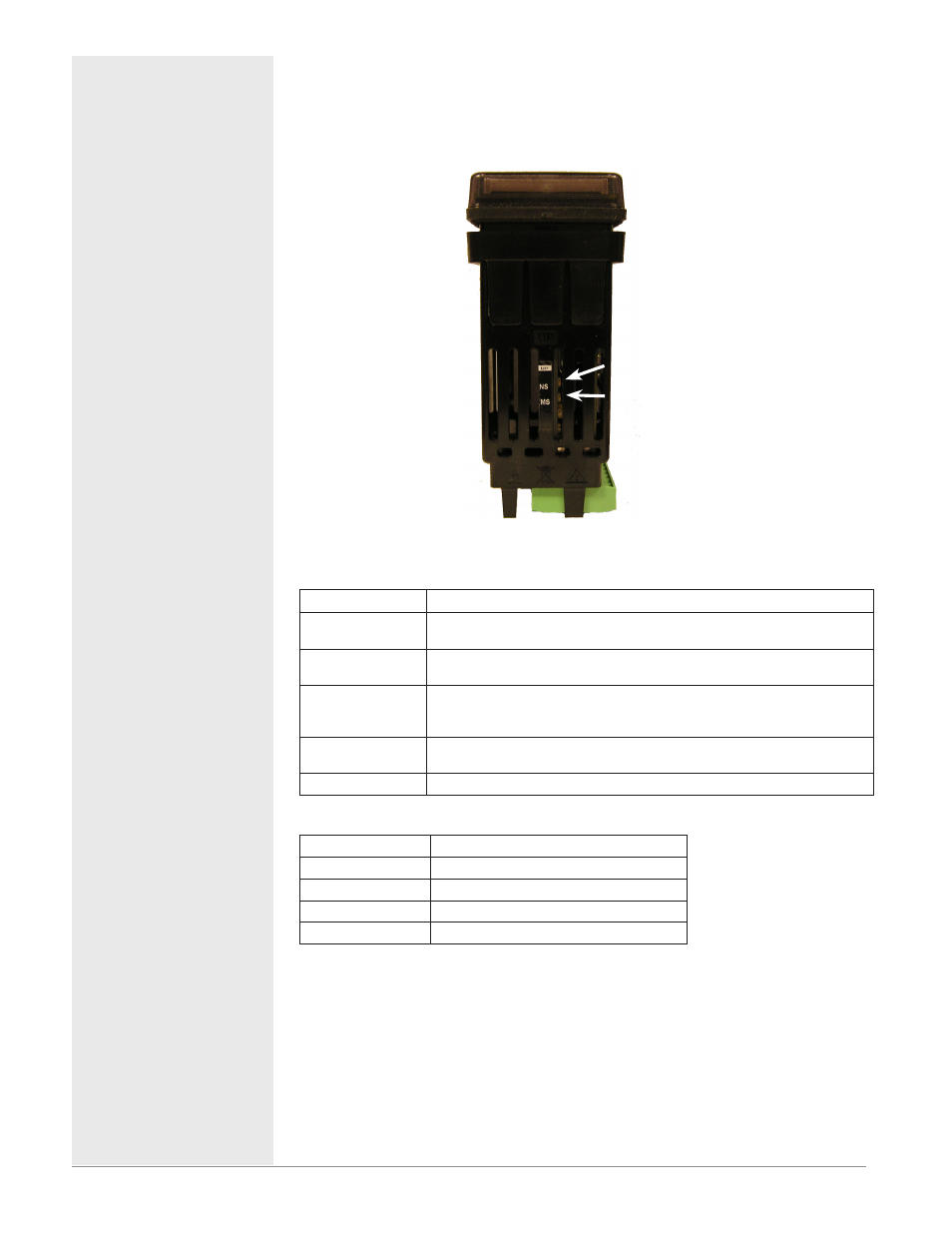
DeviceNet LED Indicators
Viewing the control from the front and then looking on top two LEDs can be
seen aligned vertically front to back. The LED closest to the front is identi-
fied as the network (Net) LED where the one next to it would be identified as
the module (Mod) LED.
Network Status
Indicator LED
Description
Off
The device is not online and has not completed the duplicate MAC ID test
yet. The device may not be powered.
Green
The device is online and has connections in the established state (allcated
to a Master).
Red
Failed communication device. The device has detected an error that has
rendered it incapable of communicating on the network (duplicate MAC ID
or Bus-off).
Flashing Green
The device is online, but no connection has been allocated or an explicit
connection has timed out.
Flashing Red
A poll connection has timed out.
Module Status
Indicator LED
Description
Off
No power is applied to the device.
Flashing Green-Red The device is performing a self-test.
Flashing Red
Major Recoverable Fault.
Red
Major Unrecoverable Fault.
Network Status
Module Status