Ethernet/ip™, pccc and modbus tcp communications, Ethernet led indicators – Watlow EZ-ZONE PM Integrated Controller User Manual
Page 38
Watlow EZ-ZONE
®
PM Integrated Controller
•
35
•
Chapter 2 Install and Wire
Warning:
Óç
Use National Electric (NEC) or other
country-specific standard wiring and
safety practices when wiring and
connecting this controller to a power
source and to electrical sensors or
peripheral devices. Failure to do so
may result in damage to equipment
and property, and/or injury or loss
of life.
Note:
Maximum wire size termination and
torque rating:
• 0.0507 to 3.30 mm
2
(30 to 12
AWG) single-wire termination or
two 1.31 mm
2
(16 AWG)
• 0.8 Nm (7.0 lb.-in.) torque
Note:
Adjacent terminals may be labeled
differently, depending on the model
number.
Note:
To prevent damage to the control-
ler, do not connect wires to unused
terminals.
Note:
Maintain electrical isolation between
analog input 1, digital input-outputs,
switched dc/open collector outputs
and process outputs to prevent
ground loops.
Note:
The control output common termi-
nal and the digital common terminal
are referenced to different voltages
and must remain isolated.
Note:
This Equipment is suitable for use in
CLASS I, DIVISION 2, Groups A, B,
C and D or Non-Hazardous locations
only. Temperature Code T4A
Warning:
ç
Explosion Hazard - Dry contact clo-
sure Digital Inputs shall not be used
in Class I Division 2 Hazardous Loca-
tions unless switch used is approved
for this application.
Warning:
ç
Explosion Hazard – Substitution of
component may impair suitability
for CLASS I, DIVISION 2.
Warning:
ç
Explosion Hazard - Do not discon-
nect while the circuit is live or
unless the area is known to be free
of ignitable concentrations of flam-
mable substances.
EIA-232/485 Modbus RTU Communications
485 common
485 T+/R+
CB
CA
CC
CB
CA
C5
C3
C2
Slot B, E
485 T-/R-
485 T+/R+
485 T-/R-
232 common
232 (TX) to DB9 pin 2 (RD)
232 (RD) to DB9 pin 3 (TX)
• Wire T-/R- to the A termi-
nal of the EIA-485 port.
• Wire T+/R+ to the B termi-
nal of the EIA-485 port.
• Wire common to the com-
mon terminal of the EIA-
485 port.
• Do not route network wires
with power wires. Connect
network wires in daisy-
chain fashion when con-
necting multiple devices in
a network.
• A termination resistor may
be required. Place a 120 Ω
resistor across T+/R+ and
T-/R- of last controller on
network.
• Do not wire to both the
EIA-485 and the EIA-232
pins at the same time.
• Two EIA-485 terminals of
T/R are provided to assist
in daisy-chain wiring.
• Do not connect more than
one EZ-ZONE PM control-
ler on an EIA-232 network.
• Do not connect more than
16 EZ-ZONE controllers on
a Standard Bus EIA-485
network.
• Maximum number of EZ-
ZONE controllers on a
Modbus network is 247.
• maximum EIA-232 network
length: 15 meters (50 feet)
• maximum EIA-485 network
length: 1,200 meters (4,000
feet)
• 1/8th unit load on EIA-485
bus.
• Communications instance 2
Slot B
PM [6] _ _ _ _ - [2] _ _ _ _ _ _
Slot E
PM [4,8,9] _ _ _ _ - [2] _ _ _
_ _ _
Modbus-IDA
Terminal
EIA/TIA-485
Name
Watlow Terminal
Label
Function
DO
A
CA or CD
T-/R-
D1
B
CB or CE
T+/R+
common
common
CC or CF
common
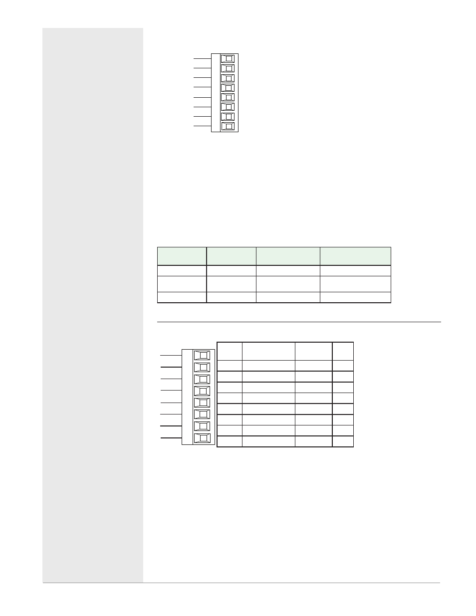
EtherNet/IP™, PCCC and Modbus TCP Communications
receive -
unused
E8
E7
E6
E5
E4
E3
E2
E1
Slot B, E
unused
unused
unused
receive +
transmit -
transmit +
RJ-45
pin
T568B wire
color
Signal
Slot
B, E
8
brown
unused
E8
7
brown & white
unused
E7
6
green
receive -
E6
5
white & blue
unused
E5
4
blue
unused
E4
3
white & green
receive +
E3
2
orange
transmit -
E2
1
white & orange
transmit + E1
EtherNet/IP™ and Modbus TCP communica-
tions to connect with a 10/100 switch .
• Do not route network
wires with power wires.
• Connect one Ethernet
cable per controller to
a 10/100 Mbps ethernet
switch. Both Modbus TCP
and EtherNet/IP™ are
available on the network.
• Communications instance
2
Slot B
PM [6] _ _ _ _ - [3] _ _ _ _
_ _
Slot E
PM[4,8,9] _ _ _ _ - [3] _ _ _
_ _ _
Note:
When changing the fixed IP address cycle module power for new address to
take effect.
Ethernet LED Indicators
Viewing the control from the front and then looking on top four LEDs can be
seen aligned vertically front to back. The LEDs are identified accordingly:
closest to the front reflects the Network (Net) Status, Module (Mod) Status is
next, Activity status follows and lastly, the LED closest to the rear of the con-
trol reflects the Link status.