Wiring – Watlow EZ-ZONE PM Integrated Controller User Manual
Page 25
Watlow EZ-ZONE
®
PM Integrated Controller
•
22
•
Chapter 2 Install and Wire
Slot A
Slot B
Slot D
Slot E
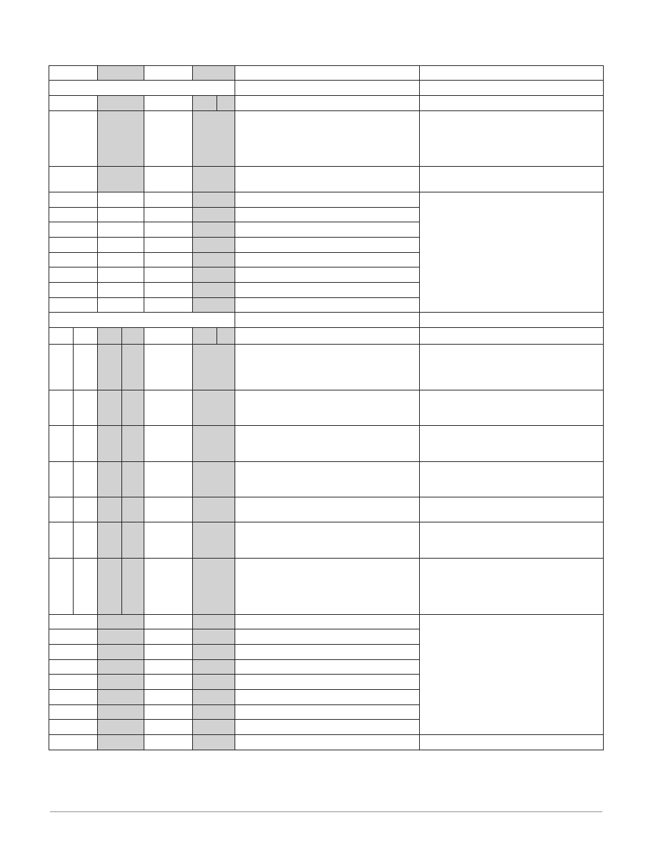
Inputs
Terminal Function
Configuration
1
2
7 - 12
T1
S1
R1
T2
S2
R2
S2 (RTD) or current +
S3 (RTD), thermocouple -, current - or volts
-, potentiometer wiper, thermistor
S1 (RTD), thermocouple + or volts +,
thermistor, potentiometer
Universal / Thermistor Input
input 1: all configurations
input 2: PM _ _ _ _ _ - _ [R,L] _ _ _ _ _
T2
S2
mA ac
mA ac
Current Transformer
PM _ _ _ _ _ - _ [T] _ _ _ _ _
B7
Common
Digital Inputs
PM[4,8,9] _ _ _ _ - [C, D] _ _ _ _ _ _
D7
digital input or output
D8
digital input or output
D9
digital input or output
D10
digital input or output
D11
digital input or output
D12
digital input or output
Z7
Internal Supply
Outputs
Terminal Function
Configuration
1
2
3
4
7 - 12
X1
W1
Y1
X3
W3
Y3
common (Any switched dc output can use
this common.)
dc- (open collector)
dc+
Switched dc/open collector
output 1: PM _ _ _ [C] _ - _ _ _ _ _ _ _
output 3: PM _ _ _ _ _ - _ _ [C] _ _ _ _
W2
Y2
W4
Y4
dc-
dc+
Switched dc
output 2: PM _ _ _ _ [C] - _ _ _ _ _ _ _
output 4: PM _ _ _ _ _ - _ _ _ [C] _ _ _
F1
G1
H1
F3
G3
H3
voltage or current -
voltage +
current +
Universal Process
output 1: PM _ _ _ [F] _ - _ _ _ _ _ _ _
output 3: PM _ _ _ _ _ - _ _ [F] _ _ _ _
L1
K1
J1
L3
K3
J3
normally open
common
normally closed
Mechanical Relay 5 A, Form C
output 1: PM _ _ _ [E] _ - _ _ _ _ _ _ _
output 3: PM _ _ _ _ _ - _ _ [E] _ _ _ _
L2
K2
L4
K4
normally open
common
NO-ARC 15 A, Form A
output 2: PM _ _ _ _ [H] - _ _ _ [H*] _ _ _
L2
K2
L4
K4
normally open
common
Mechanical Relay 5 A, Form A
output 2: PM _ _ _ _ [J] - _ _ _ _ _ _ _
output 4: PM _ _ _ _ _ - _ _ _ [J] _ _ _
L1
K1
L2
K2
L3
K3
L4
K4
normally open
common
Solid-state Relay 0.5 A, Form A
output 1: PM _ _ _ [K] _ - _ _ _ _ _ _ _
output 2: PM _ _ _ _ [K] - _ _ _ _ _ _ _
output 3: PM _ _ _ _ _ - _ _ [K] _ _ _ _
output 4: PM _ _ _ _ _ - _ _ _ [K] _ _ _
B7
Common
Digital Outputs
PM[4,8,9] _ _ _ _ - [C, D] _ _ _ _ _ _
D7
switched dc/open collector output
D8
switched dc/open collector output
D9
switched dc/open collector output
D10
switched dc/open collector output
D11
switched dc/open collector output
D12
switched dc/open collector output
Z7
Internal Supply
Slot A
Slot B
Slot D
Slot E
* Output 4, PM4, PM8 and PM9 only
Wiring