Chapter 6 system setup, Chapter 6, System setup – IAI America XSEL-KET User Manual
Page 46
27
INTELLIGENT ACTUATOR
Part 1 Installation
Chapter 6 System Setup
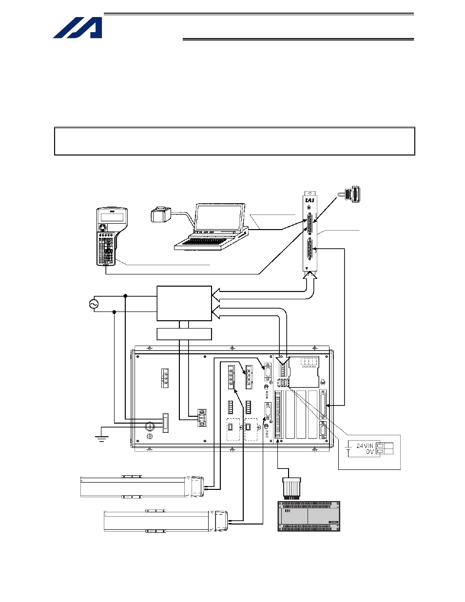
A connection example of a 2-axis controller is given below:
1. Connection Method of Controller and Actuator (Standard Specification)
Note: If multiple controller axes are used, be careful not to connect the actuator cables and connectors
wrongly. Confirm the model type of the actuator connected to each connector. Wrong
connections of actuators and connectors may lead to motor or board damage or malfunction.
Note: In the case of an absolute specification, perform an absolute reset after the connection (refer to Chapter 7).
ANSI-compatible teaching pendant
ANSI-compatible
PC cable
Relay box
AC power
source
PC
Dummy plug (AUTO)
Drive-power cutoff
control circuit
Noise filter
Class D grounding
(protective grounding)
PIO power, 24 VDC
PLC (host side)
Connection cable
between relay box
and controller