Pcon-ca/cfa, Power con – IAI America PCON-CA User Manual
Page 55
Chapter 2 Wiring
POWER CON
PCON-CA/CFA
47
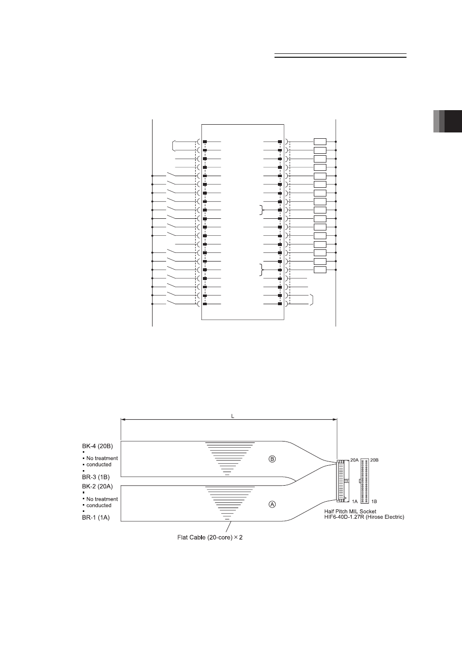
3) PIO Pattern 2 ···············256-point mode (Number of positioning points : 256-point type)
“*” in codes above shows the signal of the active low. Processing occurs when an
input signal of the type is turned OFF. An output signal of the type is normally ON
in the power-on status and turned OFF at signal output.
Ɣ Use the attached cable for the I/O connection.
Model : CB-PAC-PIOƑƑƑ (ƑƑƑ indicates the cable length L. Example. 020 2m)
0V(NPN Type)
24V DC
Supply
1A
P24
PM1
1B
0V
Supply
24V DC(NPN Type)
24V DC(PNP Type)
2A
P24
PM2
2B
0V(PNP Type)
Command Position No.1
3A
PC1
PM4
3B
Completed Position No.1
Command Position No.2
4A
PC2
PM8
4B
Completed Position No.2
Command Position No.4
5A
PC4
PM16
5B
Completed Position No.4
Command Position No.8
6A
PC8
PM32
PM64
PM128
6B
Completed Position No.8
Command Position No.16
7A
PC16
7B
Completed Position No.16
Command Position No.32
Command Position No.64
Command Position No.128
8A
PC32
PC64
PC128
8B
Completed Position No.32
Completed Position No.64
Completed Position No.128
Brake Control Release
9A
BKRL
9B
Operation Mode Changeover
10A
RMOD
RMDS
10B
Home Return
11A
HOME
HEND
11B
Pause
12A
*STP
PEND
12B
Start
13A
CSTR
SV
13B
Reset
14A
RES
*EMGS
14B
Servo ON
15A
SON
*ALM
15B
16A
16B
17A
N
17B
18A
N
18B
19A
19B
20A
20B
PCON
PIO Connector
Position Zone/Zone 1
Operating Mode Status (Manual Mode)
Home Return Completion
Position Completion
Servo ON Status
Emergency Stop Status
Alarm
BR- 1
RD- 1
OR- 1
YW- 1
GN- 1
BL- 1
PL- 1
GY- 1
WT- 1
BK- 1
BR- 2
RD- 2
OR- 2
YW- 2
GN- 2
BL- 2
PL- 2
GY- 2
WT- 2
BK- 2
BR- 3
RD- 3
OR- 3
YW- 3
GN- 3
BL- 3
PL- 3
GY- 3
WT- 3
BK- 3
BR- 4
RD- 4
OR- 4
YW- 4
GN- 4
BL- 4
PL- 4
GY- 4
WT- 4
BK- 4
PZONE
/ZONE1
LOAD
/TRQS
/*ALML
Load Output Level Status
/Torque Level Status
/Light Error Alarm