Pcon-ca/cfa, Power con – IAI America PCON-CA User Manual
Page 200
Chapter 7 I/O Parameter
POWER CON
PCON-CA/CFA
192
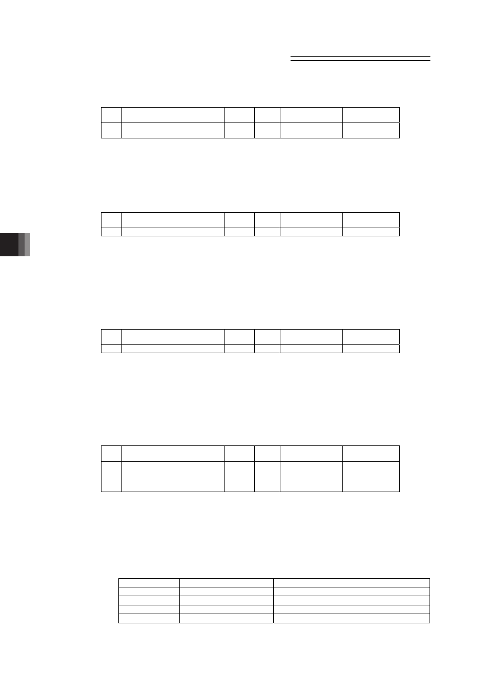
[83] High output setting (Parameter No.152)
No.
Name
Symbol
Unit
Input Range
Default factory
setting
152 High output setting
BUEN
–
0: Disable
1: Enable
0(Disabling)
Set whether use the high output function. It is necessary to equip with the actuator applicable
for the high output
(Note1)
.
(Note 1) High-output applicable actuator : RCP4 Series
[84] BU velocity loop proportional gain (Parameter No.153)
No.
Name
Symbol
Unit
Input Range
Default factory
setting
153 BU velocity loop proportional gain
BUPC
–
1 to 10000
200
When the high-thrust setting (Parameter No.152) is set effective, this parameter setting
becomes effective for Velocity Loop Proportional Gain.
[Refer to the 7.2 [24] Velocity loop proportional gain for the details]
[Reference Item] 7.2 [88] Selecting the Use of velocity loop proportional gain and velocity loop
integrated gain.
[85] BU velocity loop integral gain (Parameter No.154)
No.
Name
Symbol
Unit
Input Range
Default factory
setting
154 BU velocity loop integral gain
BUIC
–
1 to 100000
4000
When the high-thrust setting (Parameter No.152) is set effective, this parameter setting
becomes effective for Velocity Loop Integrated Gain.
[Refer to the 7.2 [25] Velocity loop integral gain for the details]
[Reference Item] 7.2 [88] Selecting the Use of velocity loop proportional gain and velocity loop
integrated gain.
[86] Absolute battery retention time (Parameter No.155)
No.
Name
Symbol
Unit
Input Range
Default factory
setting
155 Absolute battery retention time
AIP
–
0: 20 days
1: 15 days
2: 10 days
3: 5 days
0
For simple absolute type, set how long the encoder position information is to be retained after
the power to the controller is turned OFF. The setting can be selected from 4 phases and as the
motor rotation speed gets slower, the time to retain the position information gets longer. In the
case that there is a possibility that the slide or the rod of the actuator that transports the work
may be moved by an external force, follow the table below and calculate
(Note 1)
the number of
rotation from the moved speed and set this parameter to the value faster than this value. If the
motor rotation setting value exceeds the set value, the position information will be lost.
Setting
Motor rotation speed (rpm) Position information retaining time (reference)
0 (Initial setting) 100
20 days
1
200
15 days
2
400
10 days
3
800
5 days
(Note 1) Motor rotation [rpm] Moved speed [mm/s] / Lead length [mm] u 60