Chapter 9 appendix, Pcon-ca/cfa, Power con – IAI America PCON-CA User Manual
Page 225: 1 connecting example
Chapter 9
Appendix
POWER CON
PCON-CA/CFA
217
Chapter 9 Appendix
9.1
Way to Set Multiple Controllers with 1 Teaching Tool
It is usually necessary to connect the teaching tool to the controllers one by one when making a
setup to multiple controllers with one unit of teaching tool. In this section, explains how to
perform the settings without connecting and disconnecting the plug.
• Requisite devices :
(1) SIO Converter (RCB-TU-SIO-A or RCB-TU-SIO-B) : 1 unit
(2) Controller Link Cable (CB-RCB-CTL002)
: Required by the number of controllers
Accessories 1) 4-way junction (Manufactured by AMP 5-1473574-4)
: 1 unit
2) e-CON Connector (Manufactured by AMP 4-1473574-4) : 1 unit
3) Terminal Resistance (220:, with a e-CON connector)
: 1 unit
Instead of the e-CON cable attached to the controller link cable, a terminal block may be used.
In this configuration, disconnect the e-CON connector from the controller link cable.
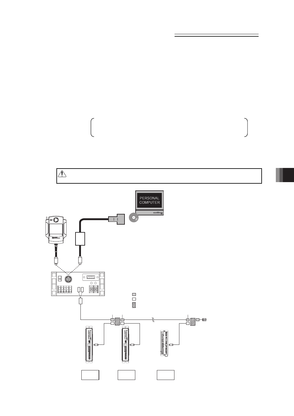
9.1.1 Connecting Example
Caution: Supply 0V to the SIO converter and each controller from the same power
source.
Teaching Pendant
To be prepared by customer.
Cable included in PC software
PC Software
(Option)
RS232C-compatible
USB-compatible
SIO Converter (with Terminal Resistor)
e-CON Connector (Manufactured by AMP 4-1473562-4 : Housing Color Green)
e-CON Connector (Manufactured by AMP 3-1473562-4 : Housing Color Orange)
Junction (Manufactured by AMP 5-1473574-4)
GN
GN
GN
Terminal Resistance
R = 220Ω
Controller Link Cable
Axis No. Setting : 0
Axis No. Setting : n-1
Axis No. Setting : 1
1st unit
nth unit
2nd unit