2 list of basic specifications, Pcon-ca/cfa, Power con – IAI America PCON-CA User Manual
Page 31: Chapter 1 specifications check
Chapter 1 Specifications Check
POWER CON
PCON-CA/CFA
23
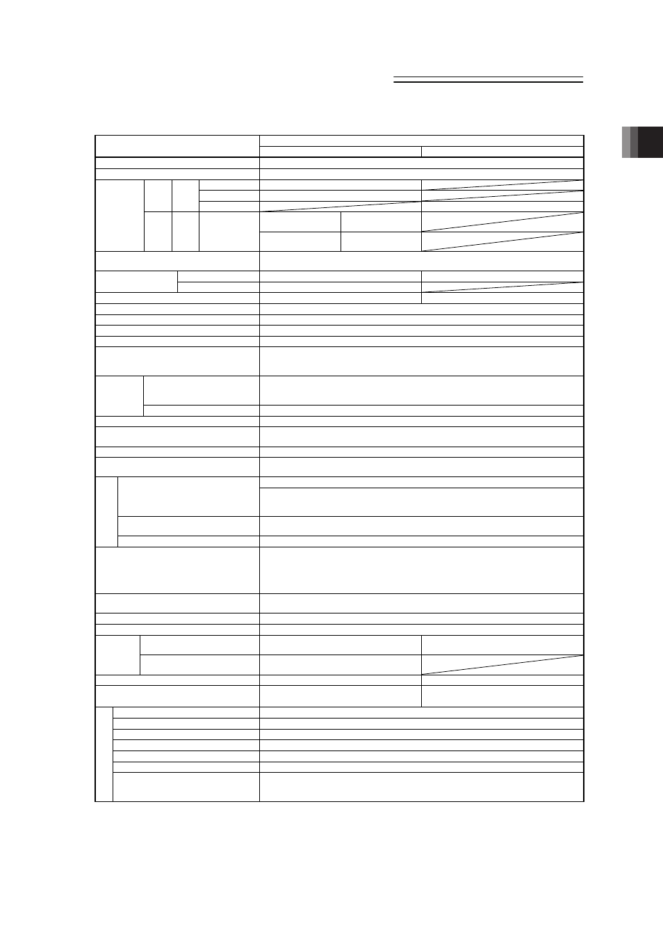
1.2
List of Basic Specifications
Description
Item
PCON-CA
PCON-CFA
Number of controlled axes
1-axis
Power-supply Voltage
24V DC r10%
20P,28P,28SP MAX. 1.0A
35P,42P,56P
MAX. 2.2A
RCP2
RCP3
Motor
Type
60P,86P
Rated 4.2A / MAX. 6A
High-thrust function
is disabled
MAX. 2.2A
Load
current
(including
control side
current
consumption)
(Note 1)
RCP4 Motor
Type
42P,56P
High-thrust function
is enabled
Rated 3.5A /
MAX. 4.2A
Power Supply for Electromagnetic Brake
(for actuator equipped with brake)
24V DC r10% 0.15A (MAX.)
RCP2, RCP3
5W
26.4W
Heat Generation
RCP4
8W
Rush Current
(Note 2)
8.3A
10A
Transient Power Cutoff Durability
MAX.500Ps
Motor Control System
Weak field-magnet vector control
Corresponding Encoder
Incremental encoder Resolution 800pulse/rev
Actuator Cable Length
MAX. 20m
Serial Communication Interface
(SIO Port)
RS485 : 1 channel (based on Modbus Protocol RTU/ASCII)
Speed : 9.6 to 230.4Kbps
Control available with serial communication in the modes other than the pulse train
PIO Type
Signal I/O dedicated for 24V DC (selected from NPN/PNP) ̖ Input 16 points max., output 16
points max.
Cable length MAX. 10m
External
Interface
Field Network Type
DeviceNet, CC-Link, PROFIBUS, CompoNet, MECHATROLINK, EtherCAT, EtherNet/IP
Data Setting and Input
PC Software, Touch Panel Teaching, Teaching Pendant
Data Retention Memory
Saves position data and parameters to non-volatile memory
(There is no limitation in number of writing.)
Operation Mode
Positioner Mode/Pulse Train Control Mode (selected by parameter setting)
Number of Positions in Positioner Mode
Standard 64 points, MAX. 512 points
(Note) Number of positions differs depending on the selection in PIO pattern.
Differential System (Line Driver System) : MAX. 200kpps Cable length MAX. 10m
Input Pulse
Open Collector System : Not applicable.
* If the host applies the open collector output, prepare AK-04 (option) separately to convert
to the differential type.
Command Pulse Multiplying Factor
(Electrical Gear : A/B)
1/50 < A/B < 50/1
Setting Range of A and B (set to parameter) : 1 to 4096
Pulse
T
rain
In
te
rfa
ce
Feedback Pulse Output
None
LED Display
(mounted on Front Panel)
SV (GN)/ALM (RD)
: Servo ON/Alarm generated
STS0 to 3
: Status display
RDY (GN)/ALM (RD)
: Absolute function in normal / absolute function error (for the simple
absolute type)
1, 0 (GN) (RD)
: Absolute function status display (for the simple absolute type)
Electromagnetic Brake Compulsory Release
Switch (mounted on Front Panel)
Switching NOM (standard)/BK RLS (compulsory release)
Insulation Resistance
500V DC 10M: or more
Protection Function against Electric Shock
Class I basic insulation
Incremental Type
Screw fixed type : 250g or less
DIN rail fixed type : 285g or less
Screw fixed type : 270g or less
DIN rail fixed type : 305g or less
Weight
(Note 3)
Simple Absolute Type
(including 190g for battery)
Screw fixed type : 450g or less
DIN rail fixed type : 485g or less
Cooling Method
Natural air-cooling
Forced air-cooling
External dimensions
Screw fixed type : 35W×178.5H×69.1D
DIN rail fixed type : 35W×185H×77.6D
Screw fixed type : 35W×190H×69.1D
DIN rail fixed type : 35W×196.3H×77.6D
Surrounding Air Temperature
0 to 40qC
Surrounding Humidity
85%RH or less (non-condensing)
Surrounding Environment
[Refer to Installation Environment]
Surrounding Storage Temperature
-20 to 70qC (Excluding battery)
Usage Altitude
1000m or lower above sea level
Protection Class
IP20
Environmen
t
Vibration Durability
Frequency 10 to 57Hz / Swing width : 0.075mm
Frequency 57 to 150Hz / Acceleration : 9.8m/s
2
XYZ Each direction Sweep time: 10 min. Number of sweep: 10 times
Note 1 Value increases in 0.3A for Field Network Type.
Note 2 In-rush current will flow for approximately 1 to 5msec after the power is turned on (at 40qC).
Note that the value of in-rush current differs depending on the impedance of the power supply line.
Note 3 Value increases in 30g for Field Network Type.