Pcon-ca/cfa, Power con – IAI America PCON-CA User Manual
Page 138
Chapter 3 Operation
POWER CON
PCON-CA/CFA
130
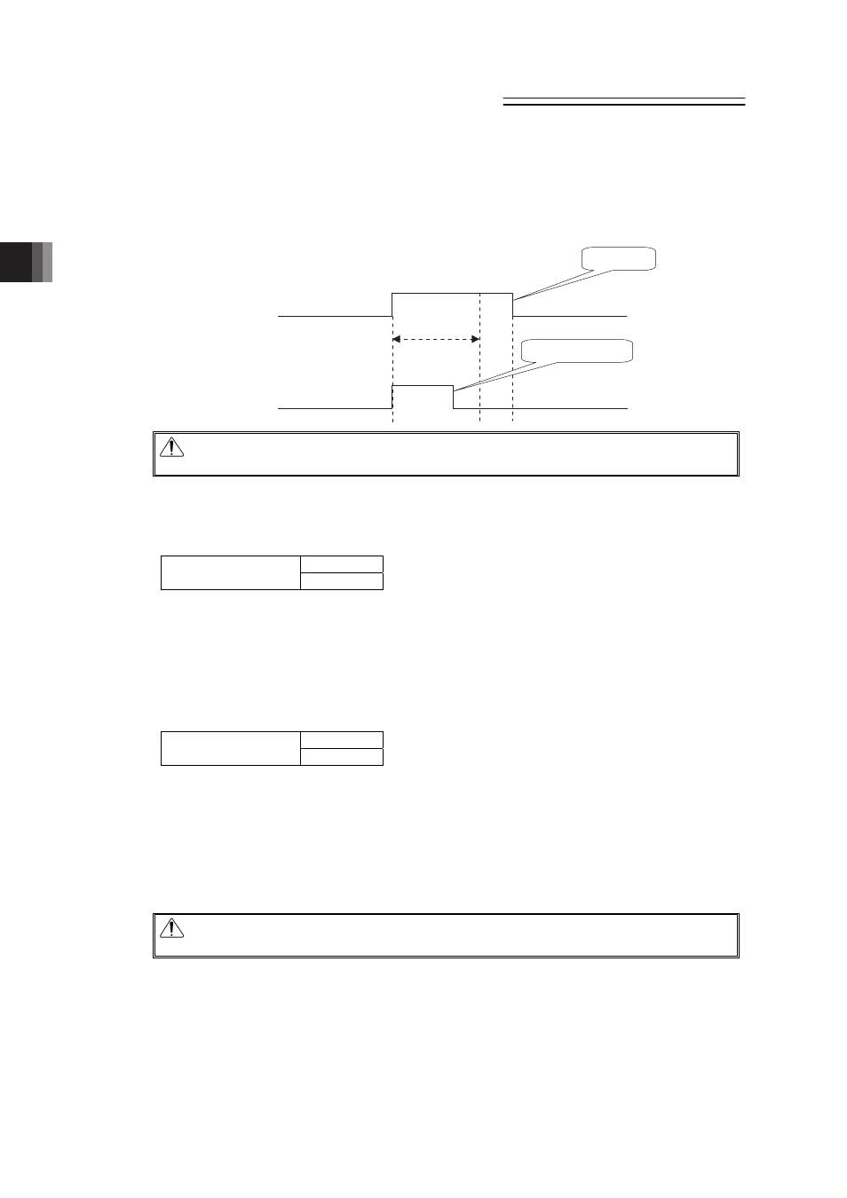
3.3.1 I/O Signal Controls
The input signals of this controller incorporate an input time constant to prevent malfunction
due to chattering, noise, etc. Make sure to input the signals continuously for 6ms or more.
(Note) Command pulse train inputs (PP•/PP, NP•/NP) do not have input time constants. Also, it
is necessary to input 16ms or more for CSTP Signal.
Caution: To use I/O signals, be sure to tilt the operation mode setting switch on the
front panel of the controller to the “AUTO” position.
3.3.2 Operation Ready and Auxiliary Signals
[1] System Ready (PWR)
Output
PIO signal
PWR
The signal is turned ON if the controller can be controlled after main power-on.
It is turned ON once the initialization terminates normally after main power-on and PCON can
be controlled regardless of alarm and servo status.
Even in the alarm condition, when the PCON can control the system, it is turned “ON”.
[2] Emergency stop status (*EMGS)
Output
PIO signal
*EMGS
1) The emergency stop status EMGS is turned ON when in normal condition and turned OFF
when EMG terminal on “2.1.3 [1] Power Supply Connector” is 0V (emergency stop
condition or disconnected).
2) It turns back ON once the emergency stop condition is released and EMG terminal goes
up to 24V DC. Have an appropriate safety treatment such as interlock with this signal for
the host controller (PLC, etc.).
Caution: It is not an emergency stop output due to an alarm generation of the
controller.
Identify
Does not identify
Input Signal
Input Signal
6ms