Pcon-ca/cfa, Power con, 2] format settings of command pulse train – IAI America PCON-CA User Manual
Page 153
Chapter 3 Operation
POWER CON
PCON-CA/CFA
145
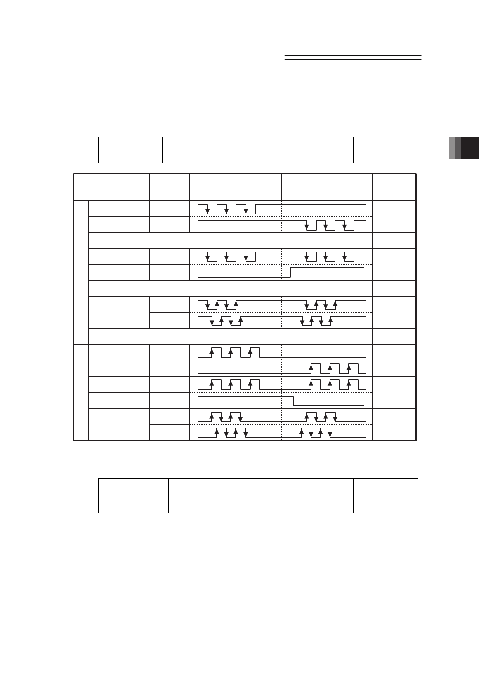
[2] Format Settings of Command Pulse Train
Set the format of command pulse train in Parameter No.63 and active high/low in No.64.
(1) Command Pulse Mode
User Parameter No.63 Command PulseInput Mode
Name
Symbol
Unit
Input Range
Initial Value
Command Pulse
Input Mode
CPMD
–
0 to 2
1
PP
•
/PP
NP
•
/NP
PP
•
/PP
NP
•
/NP
PP
•
/PP
NP
•
/NP
PP
•
/PP
NP
•
/NP
PP
•
/PP
NP
•
/NP
PP
•
/PP
NP
•
/NP
High
Low
High
Low
Normal Rotation
Pulse Train
Normal Rotation
Pulse Train
Reverse Rotation
Pulse Train
Reverse Rotation
Pulse Train
The normal rotation pulse train shows the motor rotation amount in normal direction, and
reverse rotation pulse train shows the motor rotation amount in reverse direction.
Pulse Train
Pulse Train
Symbol
Symbol
The command pulse shows the motor rotation amount and the command symbol shows the
rotation direction.
A/B Phase
Pulse Train
A/B Phase
Pulse Train
The A/B Phase 4-fold Pulse with the phase difference of 90° shows the commands for
the rotation amount and direction.
Command Pulse
Train Mode
Input
Terminal
In Normal Rotation
In Reverse Rotation
Negative Logic
Positive Logic
Setting Value
of Parameter
No. 63
2
1
0
2
1
0
(2) Command Pulse Mode Input Polarity
User Parameter No.64 Command Pulse Input Mode Polarity
Name
Symbol
Unit
Input Range
Initial Value
Command Pulse
Input Mode
Polarity
CPMD
–
0 to 1
0
Set Value
Positive logic : 0
Negative logic : 1