Starting procedures, Pcon-ca/cfa, Power con – IAI America PCON-CA User Manual
Page 27: Positioner mode
POWER CON
PCON-CA/CFA
19
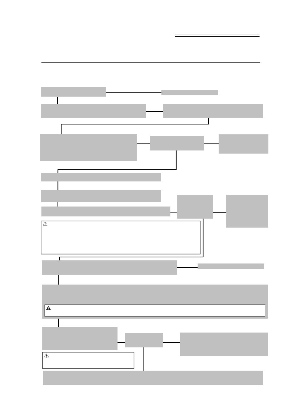
Starting Procedures
1. Positioner Mode
When using this product for the first time, make sure to avoid mistakes and incorrect wiring by
referring to the procedure below. “PC” stated in this section means “PC software”.
ω
Yes
No ψ
ω
ψ
No ψ
Contact us or our distributor.
ω
Yes
No ψ
ψ
Check Item
Is the Controller Status
Display LED turned OFF?
Connect the teaching tool
such as PC to confirm the
content of alarm and have
an appropriate treatment.
Servo ON
Turn the servo ON with the operation on the teaching tool such as PC.
Check Item
Is the Controller
Status Display
LED turned ON in
green [SV]?
Safety Circuit Check
Does the emergency stop circuit (drive cutoff circuit) work properly and turn
the servo OFF?
Check the emergency stop circuit.
Target Position Setting
Set the target position in “Position” Box in each position table.
Perform a home-return operation first when Direct Teaching is to be performed. When moving the actuator manually, set the
Brake Release Switch to “BK RLS” side for the brake equipped type. Put the switch back after the setting is complete.
ψ
No ψ
ω
Yes
Safety Speed Setting
Set the Parameter No.35 if necessary.
The safety speed is set to 100mm/s or less at the delivery.
ω
Test Run Adjustment 1
Check the operation without mounting a
work and set the safety speed invalid on
the teaching tool such as PC, and then
check the operation with a work mounted.
Check if there is any problem with the
installation of the actuator and the condition of
the actuator use exceeds the ranges of the rated
values.
Adjust the servo if necessary.
Power Supply and Alarm Check
Connect a teaching tool such as PC, turn the
operation mode setting switch to “MANU” side and
turn the power ON for unit.
Select [Teaching Mode 1 Safety Speed Activated /
PIO Operation Invalid] in the teaching tool.
If an alarm is
generated, connect
the PC or teaching
pendant and check
the content of the
alarm to have the
right treatment.
ω
Yes
φ
Yes
Test Run Adjustment 2
1) Set the operation mode setting switch to “AUTO”.
2) Output the operation command from PLC to the controller and check the system operation.
Check Item
Any vibration or
abnormal noise?
No ψ
ω
Yes
Check of Packed Items
Are there all the delivered items?
Caution To ensure safety, it is recommended
that safety speed be enabled during
initial movements.
Installation and Wiring [Refer to Chapter 1, 2.1, 2.3]
Perform the installation of and wiring for the actuator and
controller.
Caution
Please perform this process with the actuator away from the mechanical end or
interfering subjects as much as possible.
Put the actuator away if it interferes with surroundings. It may generate an alarm if the
actuator hit the mechanical end or interfering subjects when the servo is turned ON.
The slider may get slightly dropped by self-weight if servo ON and OFF is repeatedly
performed at the same position. Be careful not to pinch the hand or damage the work.
Warning In the case the actuator is installed in vertical orientation and put the brake release switch to [BK RLS] side, be
careful not to drop it with self-weight and pinch your hand or damage the work.
PIO Pattern Settings
Set the used PIO pattern to Parameter No.25.
Point Check Item
• Is frame ground (FG) connected?
• Has the noise countermeasure been taken?