Pcon-ca/cfa, Power con – IAI America PCON-CA User Manual
Page 207
Chapter 8
Troubleshooting
POWER CON
PCON-CA/CFA
199
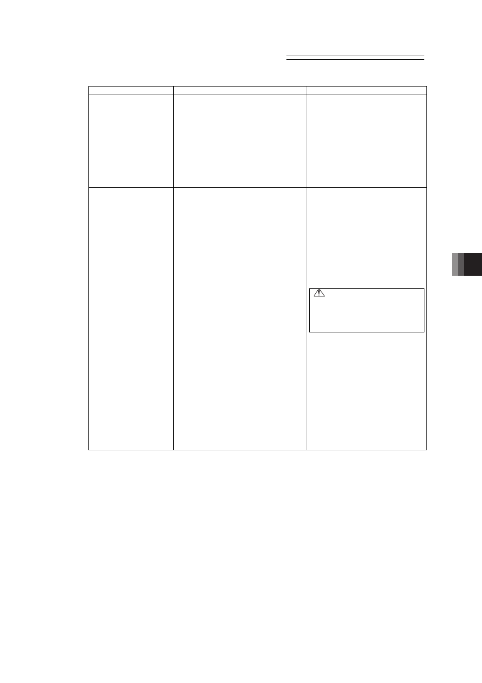
Situation
Possible cause
Check/Treatment
ALM in the status display
LEDs turns on when the
power is supplied.
(1) Occurrence of alarm
(2) During emergency-stop.
1) Was the emergency-stop switch.
2) EMG- on the power supply
connector is not connected.
(1) Check the error code with the
teaching tool being connected
and remove the cause by
referring the alarm list.
[Refer to 8.4 Alarm List.]
(2) 1) Release the emergency stop
switch.
2) Check the connection of the
power connector (EMG-).
[Refer to 2.3.1 Wiring Layout
of Power Supply Connector.]
The host controller
(PLC) cannot control
PIO (24V DC I/O).
PIO signal communication is disabled.
1) 24V DC power for PIO is not
supplied.
2) Poor contact of flat cable
3) The operation mode setting switch
on the front panel is on “MANU”
side.
4) The +/- pins of 24V DC power for
PIO are connected inversely.
1) Check the PIO power voltage. If
a single power supply is
connected with large load, the
power supply voltage may drop
or the output may be shut down
depending on power units.
2) Are the PIO cable connectors
inserted to the mating
connectors securely? Check the
input signals on the I/O monitor
of the teaching tool such as PC
software.
Caution
In I/O cable conduction check,
do not widen female pins of the
connectors. Failure to follow this
may cause poor contact.
3) Can such operation as jogging
be performed from the teaching
tool such as PC software? Set
the operation mode setting
switch on the front panel and
restart the controller.
[Refer to Name for Each Parts
and Their Functions.]
4) Reverse connection of the PIO
power supply does not affect the
input circuit but makes the
output circuit faulty. Check if the
I/O of the host controller (PLC)
operates normally.