Pcon-ca/cfa, Power con – IAI America PCON-CA User Manual
Page 139
Chapter 3 Operation
POWER CON
PCON-CA/CFA
131
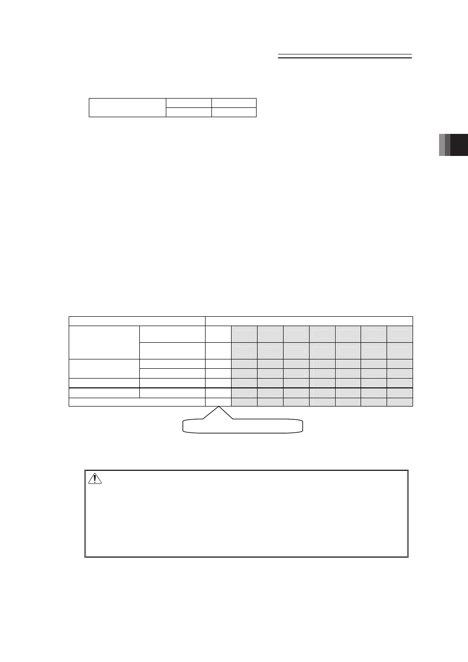
[3] Operation Mode (RMOD, RMDS)
Input
Output
PIO signal
RMOD
RMDS
{
: Available, u: Unavailable
Two operation modes are provided so that the operation by PIO signals does not overlap with
the operation by a teaching tool such as PC software through SIO (serial) communication.
The mode change is normally done by the operation mode setting switch on the front panel of
the controller.
AUTO··········Operation by PIO signals is valid.
MANU·········Operation through SIO (serial) communication is valid.
However, the controller is subject to link connection
(Note 1)
to connect with a teaching tool such
as PC software by using a SIO converter, the controller may be far apart from the teaching tool.
In such a case, the controller can be entered into the MANU mode by setting PIO signal RMOD
to ON.
Because the RMDS signal is set to ON with the MANU mode selected by using the signal,
make the operation sequence interlocked.
The table below lists the switches on the front panel, the modes selected by the RMOD signal
and the corresponding output states of the RMDS signal.
Note 1 For the details of the link connection, refer to “9.1 Way to Set Multiple Controllers with
1 Teaching Tool”.
{
: Selected or set to ON
Condition
Status
PIO Operation
Invalid
(Note 2)
{
{
{
{
u
u
u
u
Teaching tool such as
PC software
PIO Operation
Allowed
(Note 2)
u
u
u
u
{
{
{
{
AUTO
{
{
u
u
{
{
u
u
Switches on
front panel
MANU
u
u
{
{
u
u
{
{
PIO Input
RMOD
u
{
u
{
u
{
u
{
PIO Output
RMDS
u
{
{
{
u
{
{
{
PIO valid: , PIO invalid:z
z
z
z
Note 2 “PIO valid” or “PIO invalid” is the function to select a restriction while the teaching tool
such as PC software is connected.
Caution: (1) Note that selecting “PIO start enable” by using the teaching tool such as
PC software makes all PIO signals valid to enable operation however the
states of the switches and RMOD signal input may be. In this status, the
actuator may be started depending on the signals from PLC.
(2) If the teaching tool such as PC software is disconnected from the
controller, “PIO start enable” or “PIO start disable” holds the state selected
before. After teaching operation or debugging is terminated, select “PIO
start enable” and disconnect the teaching tool such as PC software from
the controller.
Operation by normal PIO