Pcon-ca/cfa, Power con – IAI America PCON-CA User Manual
Page 232
Chapter 9
Appendix
POWER CON
PCON-CA/CFA
224
[2] Wiring and setting of safety circuit
(1) Power supply
To use safety relays and/or contactors of 24V DC specification in the safety circuit, the
control power supply should be used only for the circuit as much as possible. (Do not use the
same power source as the driving power supply for this controller.)
It is the risk prevention treatment preparing for the cases such as the operation error of the
safety circuit caused by not enough power capacity.
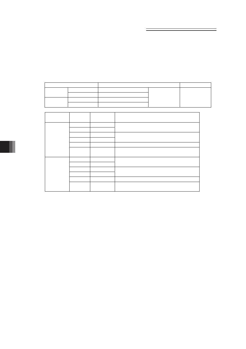
(2) Specification of system I/O connector for TP adapter
Connector Name
System I/O Connector
Applicable Wire
Cable side
FMC1.5/6-ST-3.5
(Note 1)
Upper side
(EMG side) TP adapter side MCDN1.5/6-G1-3.5P26THR
Cable side
FMC1.5/6-ST-3.5
(Note 1)
Lower side
(ENB side) TP adapter side MCDN1.5/6-G1-3.5P26THR
Phoenix Contact AWG24 to 16
(0.2 to 1.25m
2
)
Pin No.
Signal
name
Description
1
EMG1-
2
EMG1+
Emergency stop contact 1
(30V DC or less, 100mA or less)
3
EMG2-
4
EMG2+
Emergency stop contact 2
(30V DC or less, 100mA or less)
5
EMGIN
Emergency stop detection input
Upper side
(EMG side)
6
EMGOUT 24V power supply output for emergency stop
detection input
7
ENB1-
8
ENB1+
Enable contact 1
(30V DC or less, 100mA or less)
9
ENB2-
10
ENB2+
Enable contact 2
(30V DC or less, 100mA or less)
11
ENBIN
Enable detection input
Lower side
(ENB side)
12
ENBOUT 24V power supply output for enable detection
input
Note 1 Connectors on the cable side are attached under conditions where initial wiring has
been conducted.
In order to support each category, remove the initial wiring and wire your safety circuit.