3 counter unit, 1 counter initialization for asynchronous mode – Rainbow Electronics ATtiny861_V User Manual
Page 95
95
2588B–AVR–11/06
ATtiny261/461/861
16.3
Counter Unit
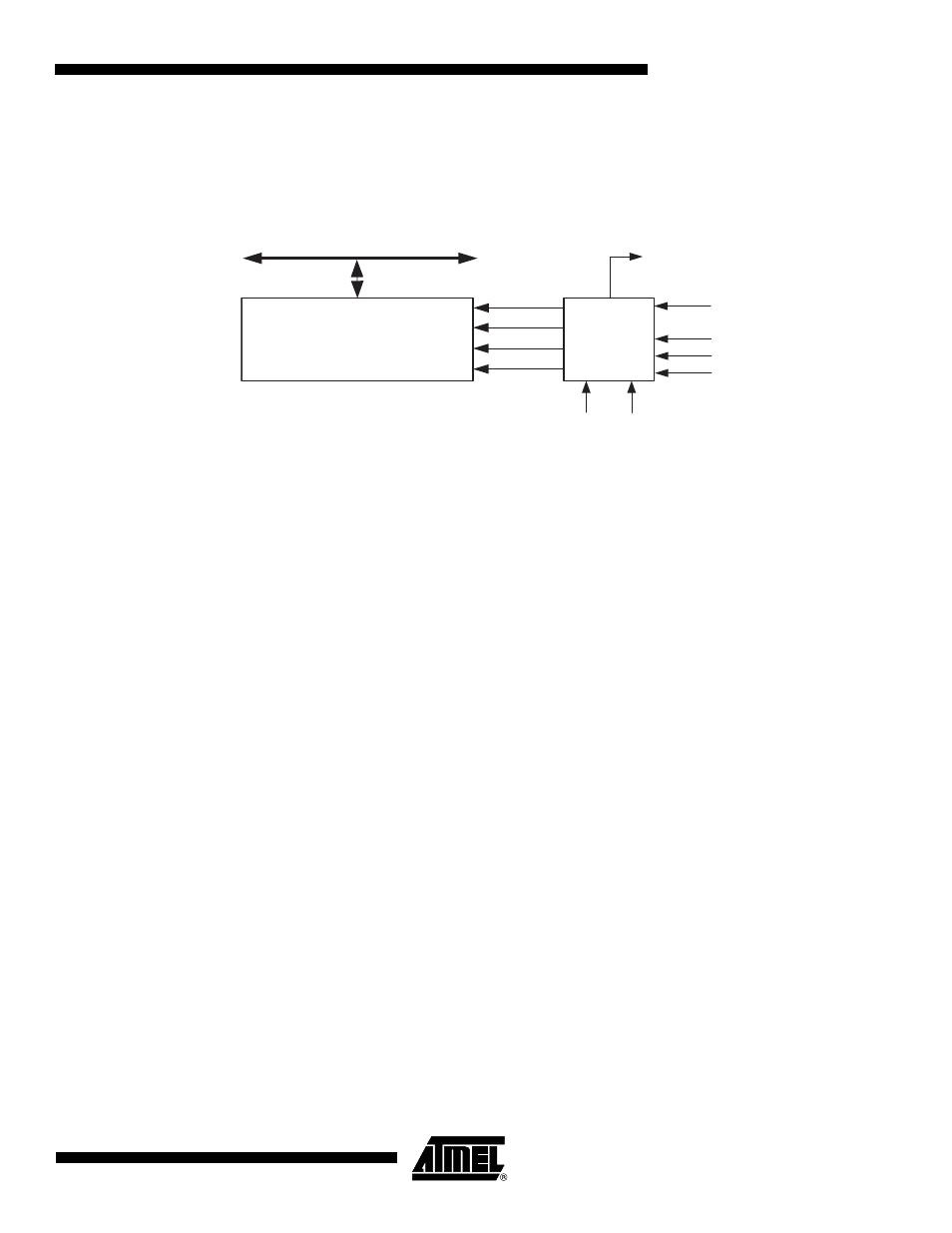
The main part of the Timer/Counter1 is the programmable bi-directional counter unit.
Figure 16-
3
shows a block diagram of the counter and its surroundings.
Figure 16-3. Counter Unit Block Diagram
Signal description (internal signals):
count
TCNT1 increment or decrement enable.
direction
Select between increment and decrement.
clear
Clear TCNT1 (set all bits to zero).
clk
Tn
Timer/Counter clock, referred to as clk
T1
in the following.
top
Signalize that TCNT1 has reached maximum value.
bottom
Signalize that TCNT1 has reached minimum value (zero).
Depending of the mode of operation used, the counter is cleared, incremented, or decremented
at each timer clock (clk
T1
). The timer clock is generated from an synchronous system clock or an
asynchronous PLL clock using the Clock Select bits (CS13:0) and the PCK Enable bit (PCKE).
When no clock source is selected (CS13:0 = 0) the timer is stopped. However, the TCNT1 value
can be accessed by the CPU, regardless of whether clk
T1
is present or not. A CPU write over-
rides (has priority over) all counter clear or count operations.
The counting sequence of the Timer/Counter1 is determined by the setting of the WGM10 and
PWM1x bits located in the Timer/Counter1 Control Registers (TCCR1A, TCCR1C and
TCCR1D). For more details about advanced counting sequences and waveform generation, see
”Modes of Operation” on page 101
. The Timer/Counter Overflow Flag (TOV1) is set according to
the mode of operation selected by the PWM1x and WGM10 bits. The Overflog Flag can be used
for generating a CPU interrupt.
16.3.1
Counter Initialization for Asynchronous Mode
To change Timer/Counter1 to the asynchronous mode follow the procedure below:
1. Enable PLL.
2. Wait 100 µs for PLL to stabilize.
3. Poll the PLOCK bit until it is set.
4. Set the PCKE bit in the PLLCSR register which enables the asynchronous mode.
DATA BUS
TCNT1
Control Logic
count
TOV1
top
Timer/Counter1 Count Enable
( From Prescaler )
bottom
direction
clear
PCK
CK
PCKE
clk
T1