6 reading the flash, 7 reading the eeprom, 8 programming the fuse low bits – Rainbow Electronics ATtiny861_V User Manual
Page 177
177
2588B–AVR–11/06
ATtiny261/461/861
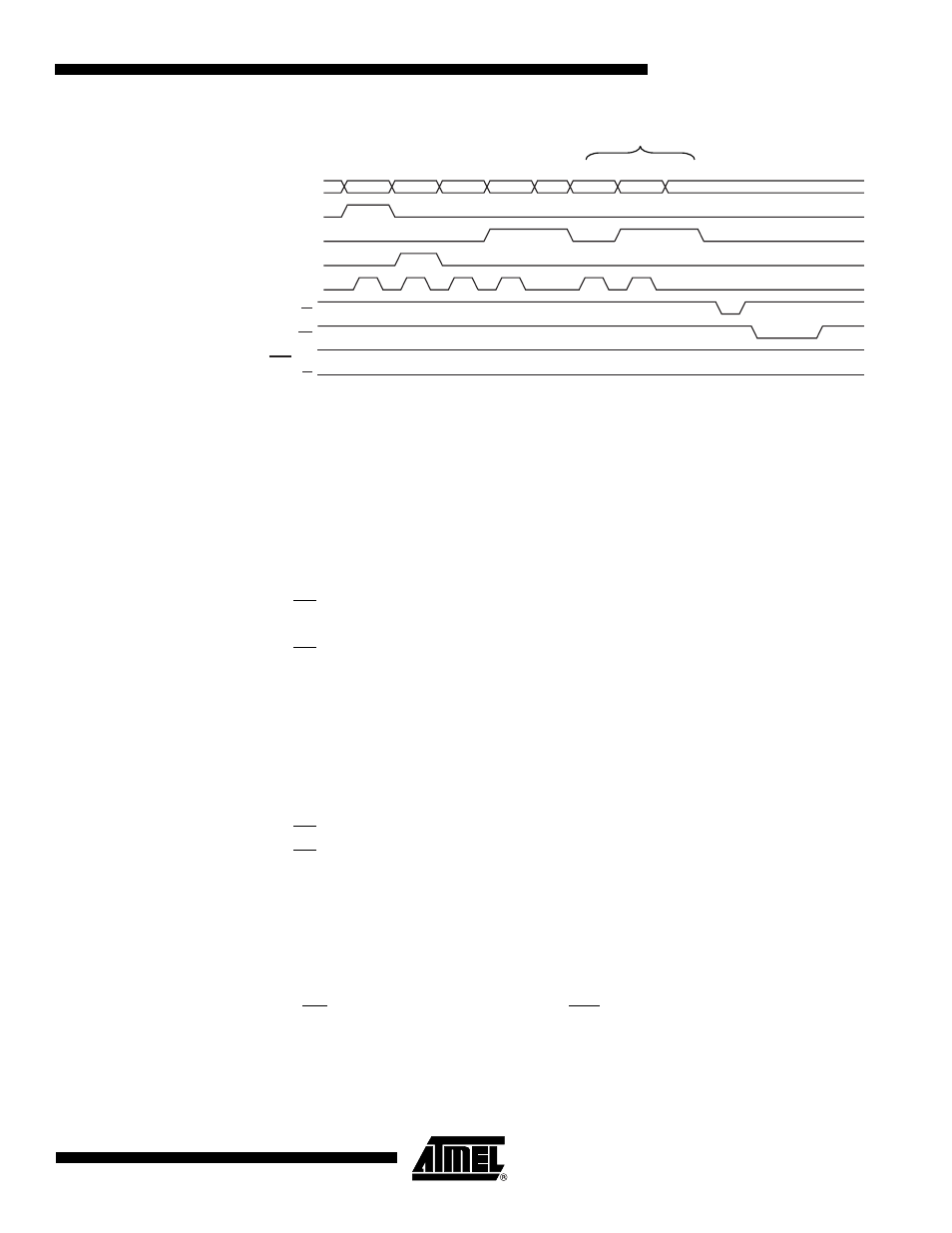
Figure 22-4. Programming the EEPROM Waveforms
22.7.6
Reading the Flash
The algorithm for reading the Flash memory is as follows (refer to
for details on Command and Address loading):
1.
A: Load Command “0000 0010”.
2.
G: Load Address High Byte (0x00 - 0xFF).
3.
B: Load Address Low Byte (0x00 - 0xFF).
4.
Set OE to “0”, and BS1 to “0”. The Flash word low byte can now be read at DATA.
5.
Set BS to “1”. The Flash word high byte can now be read at DATA.
6.
Set OE to “1”.
22.7.7
Reading the EEPROM
The algorithm for reading the EEPROM memory is as follows (refer to
for details on Command and Address loading):
1.
A: Load Command “0000 0011”.
2.
G: Load Address High Byte (0x00 - 0xFF).
3.
B: Load Address Low Byte (0x00 - 0xFF).
4.
Set OE to “0”, and BS1 to “0”. The EEPROM Data byte can now be read at DATA.
5.
Set OE to “1”.
22.7.8
Programming the Fuse Low Bits
The algorithm for programming the Fuse Low bits is as follows (refer to
for details on Command and Data loading):
1.
A: Load Command “0100 0000”.
2.
C: Load Data Low Byte. Bit n = “0” programs and bit n = “1” erases the Fuse bit.
3.
Give WR a negative pulse and wait for RDY/BSY to go high.
RDY/BSY
WR
OE
RESET +12V
0x11
ADDR. HIGH
DATA
ADDR. LOW
DATA
ADDR. LOW
DATA
XX
XA1/BS2
XA0
PAGEL/BS1
XTAL1
XX
A
G
B
C
E
B
C
E
L
K