8 adc conversion result, 1 single ended conversion, 2 unipolar differential conversion – Rainbow Electronics ATtiny861_V User Manual
Page 152
152
2588B–AVR–11/06
ATtiny261/461/861
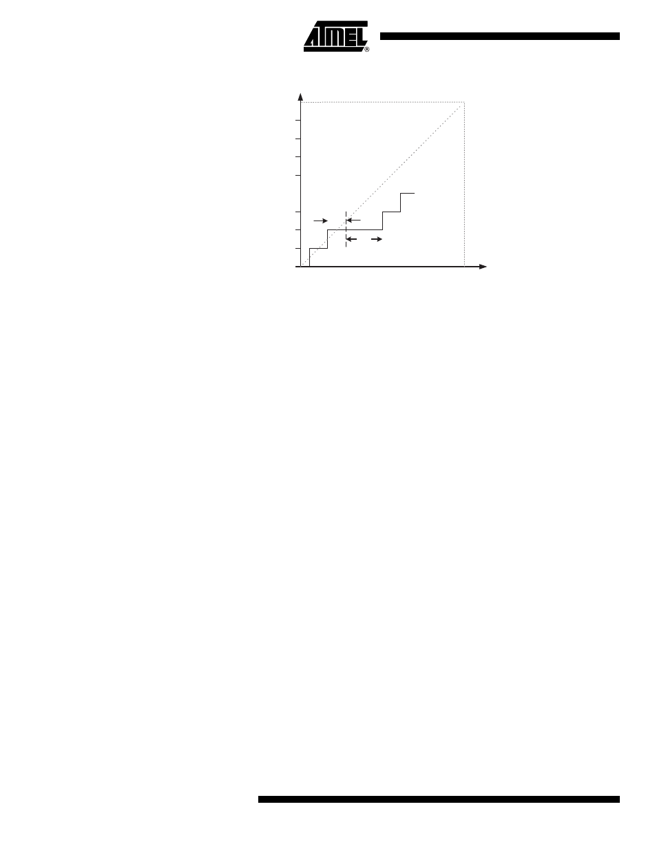
Figure 19-12. Differential Non-linearity (DNL)
• Quantization Error: Due to the quantization of the input voltage into a finite number of codes, a
range of input voltages (1 LSB wide) will code to the same value. Always ± 0.5 LSB.
• Absolute Accuracy: The maximum deviation of an actual (unadjusted) transition compared to
an ideal transition for any code. This is the compound effect of offset, gain error, differential
error, non-linearity, and quantization error. Ideal value: ± 0.5 LSB.
19.8
ADC Conversion Result
After the conversion is complete (ADIF is high), the conversion result can be found in the ADC
Result Registers (ADCL, ADCH). The form of the conversion result depends on the type of the
conversio as there are three types of conversions: single ended conversion, unipolar differential
conversion and bipolar differential conversion.
19.8.1
Single Ended Conversion
For single ended conversion, the result is
where V
IN
is the voltage on the selected input pin and V
REF
the selected voltage reference (see
Table 19-3 on page 154
and
Table 19-4 on page 155
). 0x000 represents analog ground, and
0x3FF represents the selected voltage reference minus one LSB. The result is presented in one-
sided form, from 0x3FF to 0x000.
19.8.2
Unipolar Differential Conversion
If differential channels and an unipolar input mode are used, the result is
where V
POS
is the voltage on the positive input pin, V
NEG
the voltage on the negative input pin,
and V
REF
the selected voltage reference (see
Table 19-3 on page 154
and
Table 19-4 on page
Output Code
0x3FF
0x000
0
V
REF
Input Voltage
DNL
1 LSB
ADC
V
IN
1024
⋅
V
REF
--------------------------
=
ADC
V
POS
V
NEG
–
(
) 1024
⋅
V
REF
-------------------------------------------------------- GAIN
⋅
=