12 timsk - timer/counter1 interrupt mask register – Rainbow Electronics ATtiny861_V User Manual
Page 123
123
2588B–AVR–11/06
ATtiny261/461/861
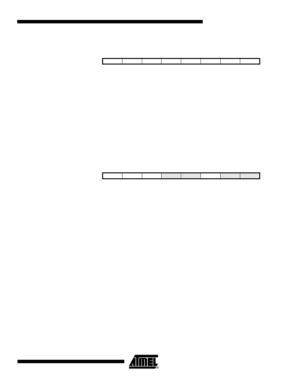
16.11.11 OCR1D – Timer/Counter1 Output Compare Register D
The output compare register D is an 8-bit read/write register.
The Timer/Counter Output Compare Register D contains data to be continuously compared with
Timer/Counter1. Actions on compare matches are specified in TCCR1A. A compare match does
only occur if Timer/Counter1 counts to the OCR1D value. A software write that sets TCNT1 and
OCR1D to the same value does not generate a compare match.
A compare match will set the compare interrupt flag OCF1D after a synchronization delay follow-
ing the compare event.
Note that, if 10-bit accuracy is used special procedures must be followed when accessing the
internal 10-bit Output Compare Registers via the 8-bit AVR data bus. These procedures are
described in section
”Accessing 10-Bit Registers” on page 110
16.11.12 TIMSK – Timer/Counter1 Interrupt Mask Register
• Bit 7- OCIE1D: Timer/Counter1 Output Compare Interrupt Enable
When the OCIE1D bit is set (one) and the I-bit in the Status Register is set (one), the
Timer/Counter1 Compare MatchD, interrupt is enabled. The corresponding interrupt at vector
$010 is executed if a compare matchD occurs. The Compare Flag in Timer/Counter1 is set (one)
in the Timer/Counter Interrupt Flag Register.
• Bit 6 - OCIE1A: Timer/Counter1 Output Compare Interrupt Enable
When the OCIE1A bit is set (one) and the I-bit in the Status Register is set (one), the
Timer/Counter1 Compare MatchA, interrupt is enabled. The corresponding interrupt at vector
$003 is executed if a compare matchA occurs. The Compare Flag in Timer/Counter1 is set (one)
in the Timer/Counter Interrupt Flag Register.
• Bit 5 - OCIE1B: Timer/Counter1 Output Compare Interrupt Enable
When the OCIE1B bit is set (one) and the I-bit in the Status Register is set (one), the
Timer/Counter1 Compare MatchB, interrupt is enabled. The corresponding interrupt at vector
$009 is executed if a compare matchB occurs. The Compare Flag in Timer/Counter1 is set (one)
in the Timer/Counter Interrupt Flag Register.
• Bit 2 - TOIE1: Timer/Counter1 Overflow Interrupt Enable
When the TOIE1 bit is set (one) and the I-bit in the Status Register is set (one), the
Timer/Counter1 Overflow interrupt is enabled. The corresponding interrupt (at vector $004) is
executed if an overflow in Timer/Counter1 occurs. The Overflow Flag (Timer1) is set (one) in the
Timer/Counter Interrupt Flag Register - TIFR.
Bit
7
6
5
4
3
2
1
0
0x2A (0x4A)
MSB
LSB
OCR1D
Read/Write
R/W
R/W
R/W
R/W
R/W
R/W
R/W
R/W
Initial value
0
0
0
0
0
0
0
0
Bit
7
6
5
4
3
2
1
0
0x39 (0x59)
OCIE1D
OCIE1A
OCIE1B
OCIE0A
OCIE0B
TOIE1
TOIE0
TICIE0
TIMSK
Read/Write
R/W
R/W
R/W
R/W
R/W
R/W
R/W
R/W
Initial value
0
0
0
0
0
0
0
0