1 compare output mode and waveform generation – Rainbow Electronics ATtiny861_V User Manual
Page 100
100
2588B–AVR–11/06
ATtiny261/461/861
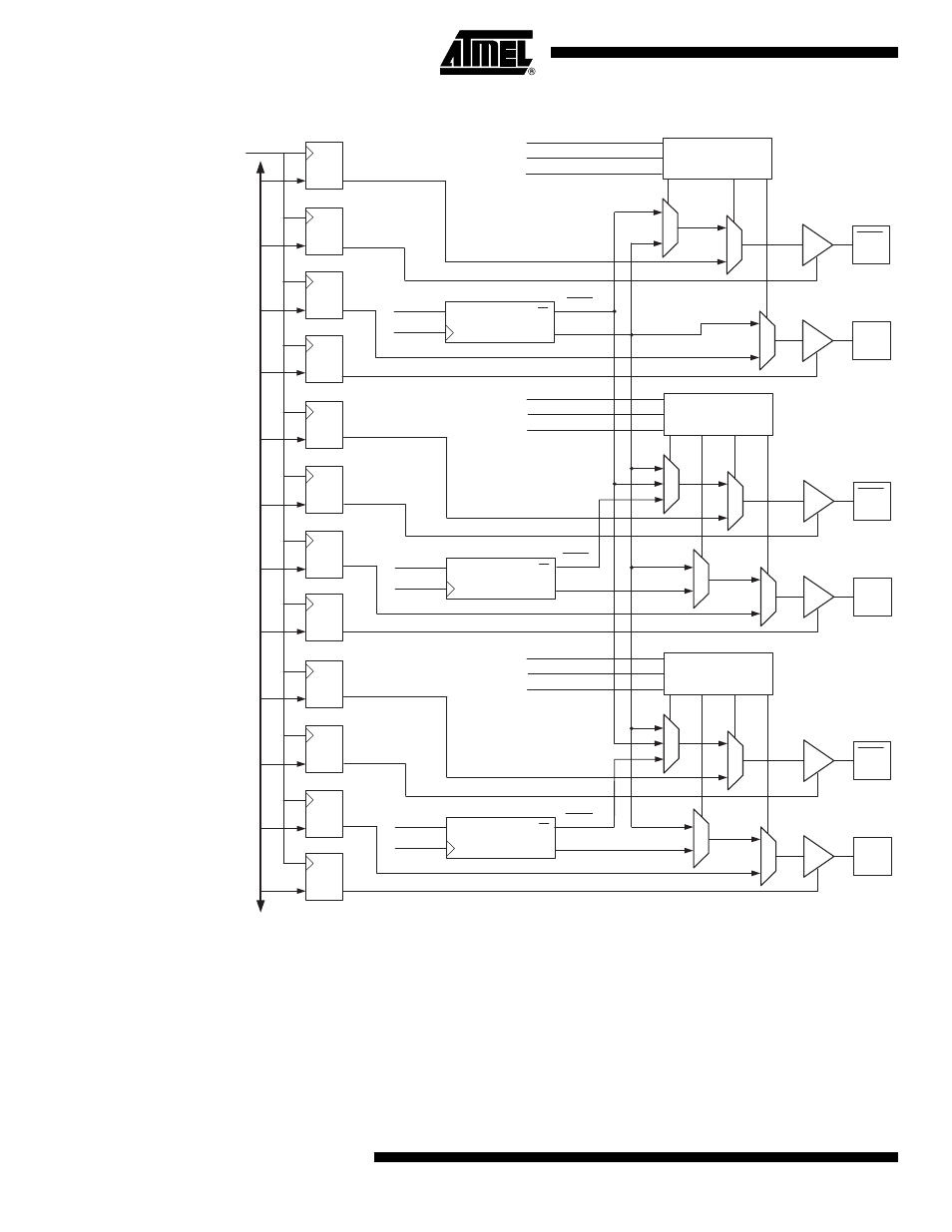
Figure 16-9. Compare Match Output Unit, Schematic
16.6.1
Compare Output Mode and Waveform Generation
The Waveform Generator uses the COM1x1:0 bits differently in Normal mode and PWM modes.
For all modes, setting the COM1x1:0 = 0 tells the Waveform Generator that no action on the
OCW1x Output is to be performed on the next Compare Match. For compare output actions in
the non-PWM modes refer to
Table 16-6 on page 113
. For fast PWM mode, refer to
Table 16-7
on page 113
, and for the Phase and Frequency Correct PWM refer to
Table 16-8 on page 114
.
A change of the COM1x1:0 bits state will have effect at the first Compare Match after the bits are
written. For non-PWM modes, the action can be forced to have immediate effect by using the
FOC1x strobe bits.
D
ATA
B
U
S
PORTB0
DDRB0
D Q
DDRB1
PORTB1
D Q
D Q
D Q
clkI/O
PORTB2
DDRB2
D Q
DDRB3
PORTB3
D Q
D Q
D Q
PORTB4
DDRB4
D Q
DDRB5
PORTB5
D Q
D Q
D Q
1
0
1
0
OC1D
PIN
2
1
0
Dead Time
Generator D
Q
Q
OCW1D
clkTn
OC1D
PIN
Output Compare
Pin Configuration
COM1D1:0
WGM11
OC1OE5:4
1
0
1
0
1
0
OC1B
PIN
2
1
0
Dead Time
Generator B
Q
Q
OCW1B
clkTn
OC1B
PIN
Output Compare
Pin Configuration
COM1B1:0
WGM11
OC1OE3:2
1
0
1
0
OC1A
PIN
0
1
Dead Time
Generator A
Q
Q
OCW1A
clkTn
OC1A
PIN
Output Compare
Pin Configuration
COM1A1:0
WGM11
OC1OE1:0
1
0
OC1A
OC1A
OC1B
OC1B
OC1D
OC1D