9 fault protection unit – Rainbow Electronics ATtiny861_V User Manual
Page 108
108
2588B–AVR–11/06
ATtiny261/461/861
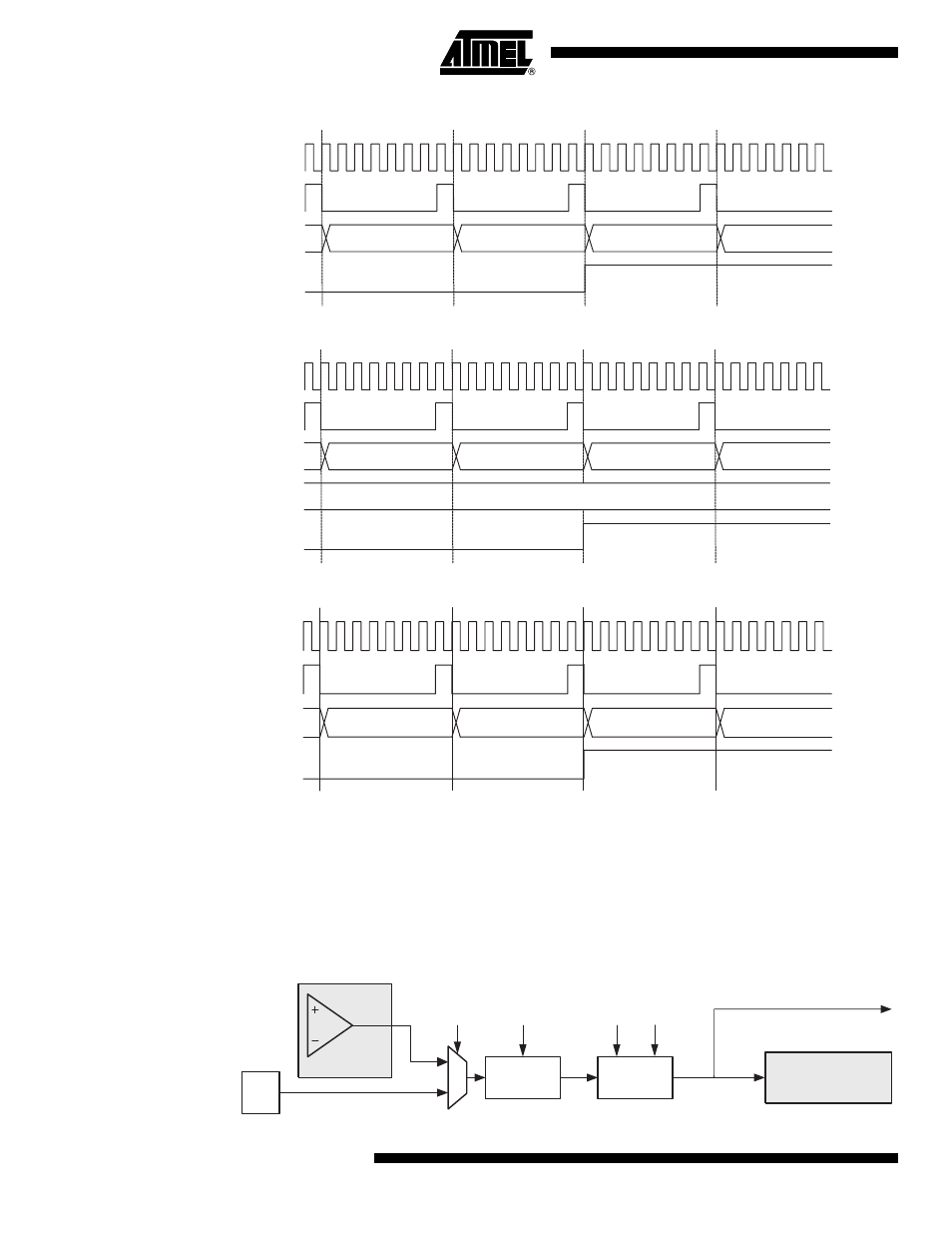
Figure 16-15. Timer/Counter Timing Diagram, with Prescaler (f
clkT1
/8)
Figure 16-16. Timer/Counter Timing Diagram, Setting of OCF1x, with Prescaler (f
clkT1
/8)
Figure 16-17. Timer/Counter Timing Diagram, with Prescaler (f
clkT1
/8)
16.9
Fault Protection Unit
The Timer/Counter1 incorporates a Fault Protection unit that can disable the PWM output pins, if
an external event is triggered. The external signal indicating an event can be applied via the
external interrupt INT0 pin or alternatively,
via the analog-comparator unit. The Fault Protection
unit is illustrated by the block diagram shown in
. The elements of the block diagram
that are not directly a part of the Fault Protection unit are gray shaded.
Figure 16-18. Fault Protection Unit Block Diagram
TOVn
TCNTn
TOP - 1
TOP
BOTTOM
BOTTOM + 1
clk
PCK
clk
Tn
(clk
PCK
/8)
OCFnx
OCRnx
TCNTn
OCRnx Value
OCRnx - 1
OCRnx
OCRnx + 1
OCRnx + 2
clk
PCK
clk
Tn
(clk
PCK
/8)
TOVn
TCNTn
BOTTOM + 1
BOTTOM + 1
BOTTOM
BOTTOM + 1
clk
PCK
clk
Tn
(clk
PCK
/8)
Analog
Comparator
Noise
Canceler
INT0
Edge
Detector
FPAC1
FPNC1
FPES1
ACO*
FPEN1
Timer/Counter1
FAULT_PROTECTION (Int. Req.)