Timer/counter0, 1 features, 2 overview – Rainbow Electronics ATtiny861_V User Manual
Page 72: 1 registers
72
2588B–AVR–11/06
ATtiny261/461/861
14. Timer/Counter0
14.1
Features
•
Clear Timer on Compare Match (Auto Reload)
•
Input Capture unit
•
Four Independent Interrupt Sources (TOV0, OCF0A, OCF0B, ICF0)
•
8-bit Mode with Two Independent Output Compare Units
•
16-bit Mode with One Independent Output Compare Unit
14.2
Overview
Timer/Counter0 is a general purpose 8-/16-bit Timer/Counter module, with two/one Output Com-
pare units and Input Capture feature.
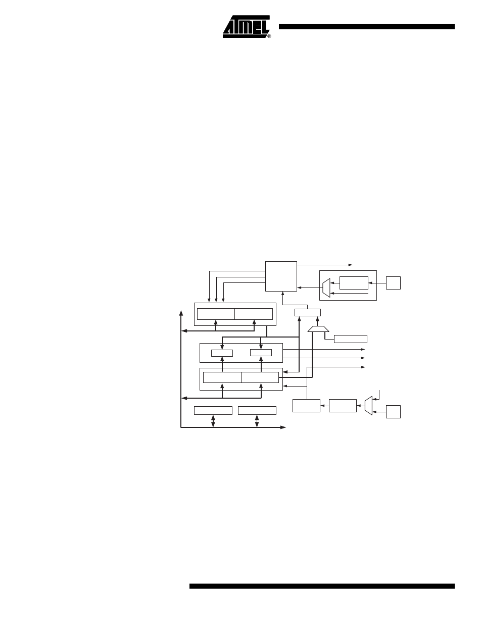
The Timer/Counter0 general operation is described in 8-/16-bit mode. A simplified block diagram
of the 8-/16-bit Timer/Counter is shown in
. For the actual placement of I/O pins, refer
to
”Pinout ATtiny261/461/861” on page 2
. CPU accessible I/O Registers, including I/O bits and
I/O pins, are shown in bold. The device-specific I/O Register and bit locations are listed in the
”Register Description” on page 84
.
Figure 14-1. 8-/16-bit Timer/Counter Block Diagram
14.2.1
Registers
The Timer/Counter0 Low Byte Register (TCNT0L) and Output Compare Registers (OCR0A and
OCR0B) are 8-bit registers. Interrupt request (abbreviated to Int.Req. in
) signals are
all visible in the Timer Interrupt Flag Register (TIFR). All interrupts are individually masked with
the Timer Interrupt Mask Register (TIMSK). TIFR and TIMSK are not shown in the figure.
In 16-bit mode the Timer/Counter consists one more 8-bit register, the Timer/Counter0 High
Byte Register (TCNT0H). Furthermore, there is only one Output Compare Unit in 16-bit mode as
the two Output Compare Registers, OCR0A and OCR0B, are combined to one 16-bit Output
Compare Register. OCR0A contains the low byte of the word and OCR0B contains the high byte
of the word. When accessing 16-bit registers, special procedures described in section
ing Registers in 16-bit Mode” on page 80
must be followed.
Clock Select
Timer/Counter
D
ATA
B
U
S
OCRnB
=
TCNTnL
Noise
Canceler
ICPn
=
Edge
Detector
Control Logic
TOP
Count
Clear
Direction
TOVn (Int. Req.)
OCnA (Int. Req.)
OCnB (Int. Req.)
ICFn (Int. Req.)
TCCRnA
TCCRnB
( From Analog
Comparator Ouput )
Tn
Edge
Detector
( From Prescaler )
clk
Tn
=
OCRnA
TCNTnH
Fixed TOP value