1 compare match blocking by tcnt0 write, 2 using the output compare unit, 8 timer/counter timing diagrams – Rainbow Electronics ATtiny861_V User Manual
Page 78
78
2588B–AVR–11/06
ATtiny261/461/861
when the interrupt is executed. Alternatively, the flag can be cleared by software by writing a log-
ical one to its I/O bit location.
shows a block diagram of the Output Compare unit.
Figure 14-4. Output Compare Unit, Block Diagram
14.7.1
Compare Match Blocking by TCNT0 Write
All CPU write operations to the TCNT0H/L Register will block any Compare Match that occur in
the next timer clock cycle, even when the timer is stopped. This feature allows OCR0A/B to be
initialized to the same value as TCNT0 without triggering an interrupt when the Timer/Counter
clock is enabled.
14.7.2
Using the Output Compare Unit
Since writing TCNT0H/L will block all Compare Matches for one timer clock cycle, there are risks
involved when changing TCNT0H/L when using the Output Compare Unit, independently of
whether the Timer/Counter is running or not. If the value written to TCNT0H/L equals the
OCR0A/B value, the Compare Match will be missed.
14.8
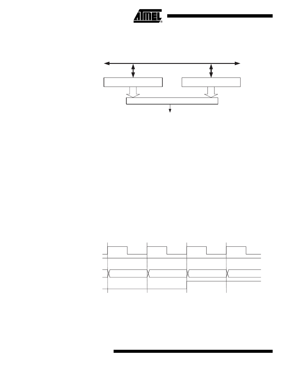
Timer/Counter Timing Diagrams
The Timer/Counter is a synchronous design and the timer clock (clk
T0
) is therefore shown as a
clock enable signal in the following figures. The figures include information on when Interrupt
Flags are set.
contains timing data for basic Timer/Counter operation. The figure
shows the count sequence close to the MAX value.
Figure 14-5. Timer/Counter Timing Diagram, no Prescaling
shows the same timing data, but with the prescaler enabled.
OCFnx (Int.Req.)
=
(8/16-bit Comparator )
OCRnx
DATA BUS
TCNTn
clk
Tn
(clk
I/O
/1)
TOVn
clk
I/O
TCNTn
MAX - 1
MAX
BOTTOM
BOTTOM + 1