5 modes of operation, 1 normal 8-bit mode, 2 clear timer on compare match (ctc) 8-bit mode – Rainbow Electronics ATtiny861_V User Manual
Page 74
74
2588B–AVR–11/06
ATtiny261/461/861
internal clock source, selected by the Clock Select bits (CS02:0). When no clock source is
selected (CS02:0 = 0) the timer is stopped. However, the TCNT0 value can be accessed by the
CPU, regardless of whether clk
T0
is present or not. A CPU write overrides (has priority over) all
counter clear or count operations. The Timer/Counter Overflow Flag (TOV0) is set when the
counter reaches the maximum value and it can be used for generating a CPU interrupt.
14.5
Modes of Operation
The mode of operation is defined by the Timer/Counter Width (TCW0), Input Capture Enable
(ICEN0) and Wave Generation Mode (WGM00) bits in
”TCCR0A – Timer/Counter0 Control Reg-
.
Table 14-3
shows the different Modes of Operation.
14.5.1
Normal 8-bit Mode
In the Normal 8-bit mode, see
Table 14-3 on page 74
, the counter (TCNT0L) is incrementing
until it overruns when it passes its maximum 8-bit value (MAX = 0xFF) and then restarts from the
bottom (0x00). The Overflow Flag (TOV0) will be set in the same timer clock cycle as the
TCNT0L becomes zero. The TOV0 Flag in this case behaves like a ninth bit, except that it is only
set, not cleared. However, combined with the timer overflow interrupt that automatically clears
the TOV0 Flag, the timer resolution can be increased by software. There are no special cases to
consider in the Normal 8-bit mode, a new counter value can be written anytime. The Output
Compare Unit can be used to generate interrupts at some given time.
14.5.2
Clear Timer on Compare Match (CTC) 8-bit Mode
In Clear Timer on Compare or CTC mode, see
Table 14-3 on page 74
, the OCR0A Register is
used to manipulate the counter resolution. In CTC mode the counter is cleared to zero when the
counter value (TCNT0) matches the OCR0A. The OCR0A defines the top value for the counter,
hence also its resolution. This mode allows greater control of the Compare Match output fre-
quency. It also simplifies the operation of counting external events.
The timing diagram for the CTC mode is shown in
Figure 14-2
. The counter value (TCNT0)
increases until a Compare Match occurs between TCNT0 and OCR0A, and then counter
(TCNT0) is cleared.
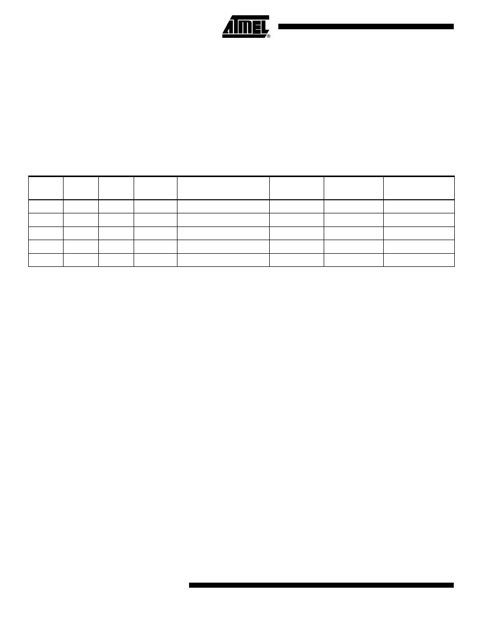
Table 14-3.
Modes of operation
Mode
ICEN0
TCW0
WGM00
Timer/Counter Mode
of Operation
TOP
Update of
OCRx at
TOV Flag
Set on
0
0
0
0
Normal 8-bit Mode
0xFF
Immediate
MAX (0xFF)
1
0
0
1
8-bit CTC
OCR0A
Immediate
MAX (0xFF)
2
0
1
X
16-bit Mode
0xFFFF
Immediate
MAX (0xFFFF)
3
1
0
X
8-bit Input Capture Mode
0xFF
Immediate
MAX (0xFF)
4
1
1
X
16-bit Input Capture Mode
0xFFFF
Immediate
MAX (0xFFFF)