2 clock sources, 3 default clock source, 4 external clock – Rainbow Electronics ATtiny861_V User Manual
Page 26
26
2588B–AVR–11/06
ATtiny261/461/861
7.2
Clock Sources
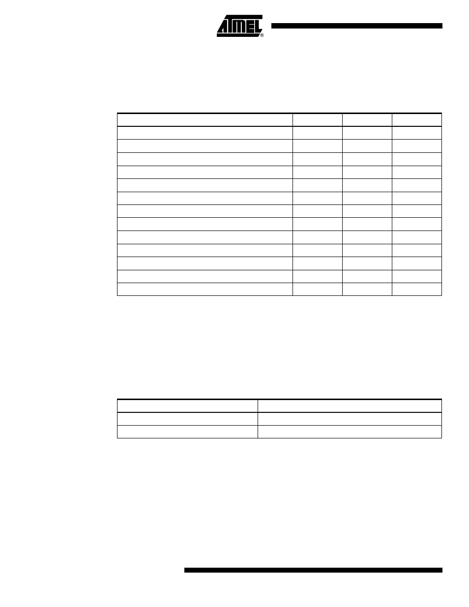
The device has the following clock source options, selectable by Flash Fuse bits as shown
below. The clock from the selected source is input to the AVR clock generator, and routed to the
appropriate modules.
Note:
1. For all fuses “1” means unprogrammed while “0” means programmed.
The various choices for each clocking option is given in the following sections. When the CPU
wakes up from Power-down or Power-save, the selected clock source is used to time the start-
up, ensuring stable Oscillator operation before instruction execution starts. When the CPU starts
from reset, there is an additional delay allowing the power to reach a stable level before com-
mencing normal operation. The Watchdog Oscillator is used for timing this real-time part of the
start-up time. The number of WDT Oscillator cycles used for each time-out is shown in
Table 7-
2
.
7.3
Default Clock Source
The device is shipped with CKSEL = “0010”, SUT = “10”, and CKDIV8 programmed. The default
clock source setting is therefore the Internal RC Oscillator running at 8 MHz with longest start-up
time and an initial system clock prescaling of 8. This default setting ensures that all users can
make their desired clock source setting using an In-System or High-voltage Programmer.
7.4
External Clock
To drive the device from an external clock source, CLKI should be driven as shown in
Figure 7-
3
. To run the device on an external clock, the CKSEL Fuses must be programmed to “0000”.
Table 7-1.
Device Clocking Options Select
(1)
vs. PB4 and PB5 Functionality
Device Clocking Option
CKSEL3..0
PB4
PB5
External Clock
0000
XTAL1
I/O
PLL Clock
0001
I/O
I/O
Calibrated Internal RC Oscillator 8.0 MHz
0010
I/O
I/O
Watchdog Oscillator 128 kHz
0011
I/O
I/O
External Low-frequency Oscillator
01xx
XTAL1
XTAL2
External Crystal/Ceramic Resonator (0.4 - 0.9 MHz)
1000
XTAL1
XTAL2
External Crystal/Ceramic Resonator (0.4 - 0.9 MHz)
1001
XTAL1
XTAL2
External Crystal/Ceramic Resonator (0.9 - 3.0 MHz)
1010
XTAL1
XTAL2
External Crystal/Ceramic Resonator (0.9 - 3.0 MHz)
1011
XTAL1
XTAL2
External Crystal/Ceramic Resonator (3.0 - 8.0 MHz)
1100
XTAL1
XTAL2
External Crystal/Ceramic Resonator (3.0 - 8.0 MHz)
1101
XTAL1
XTAL2
External Crystal/Ceramic Resonator (8.0 - 20.0 MHz)
1110
XTAL1
XTAL2
External Crystal/Ceramic Resonator (8.0 - 20.0 MHz)
1111
XTAL1
XTAL2
Table 7-2.
Number of Watchdog Oscillator Cycles
Typ Time-out
Number of Cycles
4 ms
512
64 ms
8K (8,192)