1 register description, 1 tccr0b - timer/counter0 control register b – Rainbow Electronics ATtiny861_V User Manual
Page 70
70
2588B–AVR–11/06
ATtiny261/461/861
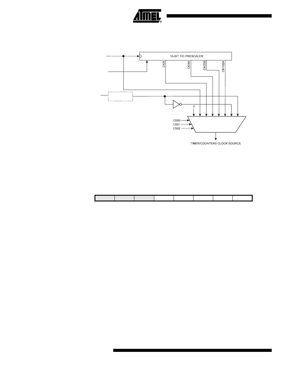
An external clock source can not be prescaled.
Figure 13-2. Prescaler for Timer/Counter0
Note:
1. The synchronization logic on the input pins (
T0)
is shown in
13.1
Register Description
13.1.1
TCCR0B – Timer/Counter0 Control Register B
• Bit 4 – TSM: Timer/Counter Synchronization Mode
Writing the TSM bit to one activates the Timer/Counter Synchronization mode. In this mode, the
value that is written to the PSR0 bit is kept, hence keeping the Prescaler Reset signal asserted.
This ensures that the Timer/Counter is halted and can be configured without the risk of advanc-
ing during configuration. When the TSM bit is written to zero, the PSR0 bit is cleared by
hardware, and the Timer/Counter start counting.
• Bit 3 – PSR0: Prescaler Reset Timer/Counter0
When this bit is one, the Timer/Counter0 prescaler will be Reset. This bit is normally cleared
immediately by hardware, except if the TSM bit is set.
• Bits 2, 1, 0 – CS02, CS01, CS00: Clock Select0, Bit 2, 1, and 0
The Clock Select0 bits 2, 1, and 0 define the prescaling source of Timer0.
PSR0
Clear
clk
T0
T0
clk
I/O
Synchronization
Bit
7
6
5
4
3
2
1
0
0x33 (0x53)
-
-
-
TSM
PSR0
CS02
CS01
CS01
TCCR0B
Read/Write
R
R
R
R/W
R/W
R/W
R/W
R/W
Initial Value
0
0
0
0
0
0
0
0