5 brown-out detection, 6 watchdog reset, For details on how to – Rainbow Electronics ATtiny861_V User Manual
Page 41
41
2588B–AVR–11/06
ATtiny261/461/861
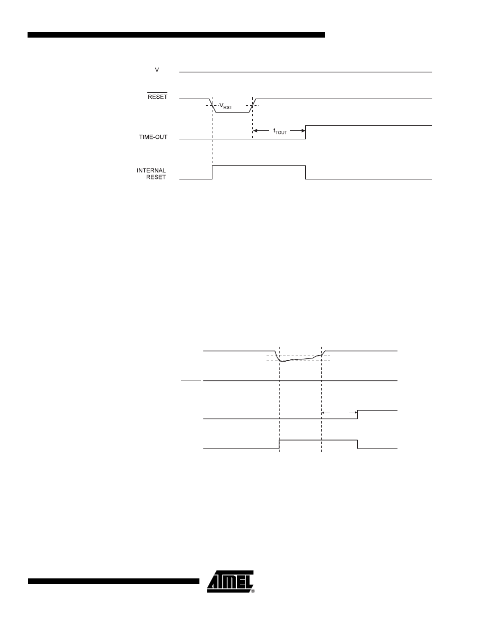
Figure 9-4.
External Reset During Operation
9.0.5
Brown-out Detection
ATtiny261/461/861 has an On-chip Brown-out Detection (BOD) circuit for monitoring the V
CC
level during operation by comparing it to a fixed trigger level. The trigger level for the BOD can
be selected by the BODLEVEL Fuses. The trigger level has a hysteresis to ensure spike free
Brown-out Detection. The hysteresis on the detection level should be interpreted as V
BOT+
=
V
BOT
+ V
HYST
/2 and V
BOT-
= V
BOT
- V
HYST
/2.
When the BOD is enabled, and V
CC
decreases to a value below the trigger level (V
BOT-
in
Figure
9-5
), the Brown-out Reset is immediately activated. When V
CC
increases above the trigger level
(V
BOT+
in
Figure 9-5
), the delay counter starts the MCU after the Time-out period t
TOUT
has
expired.
The BOD circuit will only detect a drop in V
CC
if the voltage stays below the trigger level for
longer than t
BOD
”System and Reset Characteristics” on page 189
.
Figure 9-5.
Brown-out Reset During Operation
9.0.6
Watchdog Reset
When the Watchdog times out, it will generate a short reset pulse of one CK cycle duration. On
the falling edge of this pulse, the delay timer starts counting the Time-out period t
TOUT
. Refer to
for details on operation of the Watchdog Timer.
CC
V
CC
RESET
TIME-OUT
INTERNAL
RESET
V
BOT-
V
BOT+
t
TOUT