Rainbow Electronics ATtiny861_V User Manual
Page 25
25
2588B–AVR–11/06
ATtiny261/461/861
7.1.5
Internal PLL for Fast Peripheral Clock Generation - clk
PCK
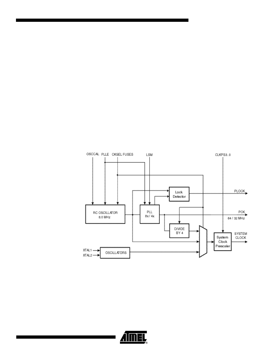
The internal PLL in ATtiny261/461/861 generates a clock frequency that is 8x or 4x multiplied
from a source input depending on the Low Speed Mode (LSM) bit. The source of the PLL input
clock is the output of the internal RC oscillator having a frequency of 8.0 MHz. Thus the output of
the PLL, the fast peripheral clock is 64 MHz or 32 MHz. The fast peripheral clock, or a clock
prescaled from that, can be selected as the clock source for Timer/Counter1. See the
Figure 7-2
on page 25
.
The PLL is locked on the RC oscillator and adjusting the RC oscillator via OSCCAL register will
adjust the fast peripheral clock at the same time. However, even if the RC oscillator is taken to a
higher frequency than 8 MHz, the fast peripheral clock frequency saturates at 85 MHz (worst
case) and remains oscillating at the maximum frequency. It should be noted that the PLL in this
case is not locked any longer with the RC oscillator clock.
Therefore, it is recommended not to take the OSCCAL adjustments to a higher frequency than 8
MHz in order to keep the PLL in the correct operating range. The internal PLL is enabled only
when the PLLE bit in the register PLLCSR is set or the CKSEL fuses are programmed to ‘0001’.
The bit PLOCK from the register PLLCSR is set when PLL is locked.
Both internal RC oscillator and PLL are switched off in power down and stand-by sleep modes.
Figure 7-2.
PCK Clocking System