Rainbow Electronics ATtiny861_V User Manual
Page 141
141
2588B–AVR–11/06
ATtiny261/461/861
18.2.1
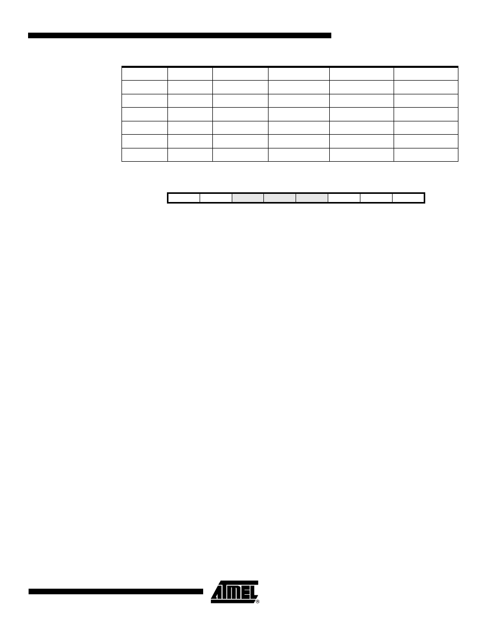
ACSRB – Analog Comparator Control and Status Register B
• Bit 7 – HSEL: Hysteresis Select
When this bit is written logic one, the hysteresis of the Analog Comparator is switched on. The
hysteresis level is selected by the HLEV bit.
• Bit 6 – HLEV: Hysteresis Level
When the hysteresis is enabled by the HSEL bit, the Hysteresis Level, HLEV, bit selects the hys-
teresis level that is either 20mV (HLEV=0) or 50mV (HLEV=1).
• Bit 2:0 – ACM2:ACM0: Analog Comparator Multiplexer
The Analog Comparator multiplexer bits select the positive and negative input pins of the Analog
Comparator. The different settings are shown in
.
1
0
001001
000
AIN0
ADC9
1
0
001001
01x
AIN1
ADC9
1
0
001001
1xx
AIN2
ADC9
1
0
001010
000
AIN0
ADC10
1
0
001010
01x
AIN1
ADC10
1
0
001010
1xx
AIN2
ADC10
Table 18-2.
Analog Comparator Multiplexed Input (Continued)
ACME
ADEN
MUX5..0
ACM2..0
Positive Input
Negative Input
Bit
7
6
5
4
3
2
1
0
0x09 (0x29)
HSEL
HLEV
-
-
-
ACM2
ACM1
ACM0
ACSRB
Read/Write
R/W
R/W
R
R
R
R/W
R/W
R/W
Initial Value
0
0
N/A
0
0
0
0
0