5 high frequency pll clock - pllclk, 5 high frequency pll clock - pll – Rainbow Electronics ATtiny861_V User Manual
Page 27
27
2588B–AVR–11/06
ATtiny261/461/861
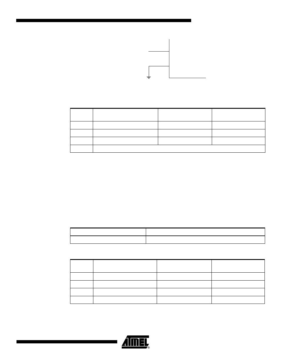
Figure 7-3.
External Clock Drive Configuration
When this clock source is selected, start-up times are determined by the SUT Fuses as shown in
Table 7-3
.
Note that the System Clock Prescaler can be used to implement run-time changes of the internal
clock frequency while still ensuring stable operation. Refer to
”System Clock Prescaler” on page
for details.
7.5
High Frequency PLL Clock - PLL
CLK
There is an internal PLL that provides nominally 64 MHz clock rate locked to the RC Oscillator
for the use of the Peripheral Timer/Counter1 and for the system clock source. When selected as
a system clock source, by programming the CKSEL fuses to ‘0001’, it is divided by four like
shown in
Table 7-4
. When this clock source is selected, start-up times are determined by the
SUT fuses as shown in
Table 7-5
. See also
”PCK Clocking System” on page 25
.
Table 7-3.
Start-up Times for the External Clock Selection
SUT1..0
Start-up Time from Power-
down and Power-save
Additional Delay from
Reset
Recommended Usage
00
6 CK
14CK
BOD enabled
01
6 CK
14CK + 4 ms
Fast rising power
10
6 CK
14CK + 64 ms
Slowly rising power
11
Reserved
EXTERNAL
CLOCK
SIGNAL
CLKI
GND
Table 7-4.
PLLCK Operating Modes
CKSEL3..0
Nominal Frequency
0001
16 MHz
Table 7-5.
Start-up Times for the PLLCK
SUT1..0
Start-up Time from Power
Down
Additional Delay from
Reset (V
CC
= 5.0V)
Recommended usage
00
1K (1024) + 4 ms
14CK + 4 ms
BOD enabled
01
16K (16384) + 4 ms
14CK + 4 ms
Fast rising power
10
1K (1024) + 64 ms
14CK + 4 ms
Slowly rising power
11
16K (16384) + 64 ms
14CK + 4 ms
Slowly rising power