1 internal voltage reference, 2 watchdog timer, Internal volt – Rainbow Electronics ATtiny861_V User Manual
Page 42
42
2588B–AVR–11/06
ATtiny261/461/861
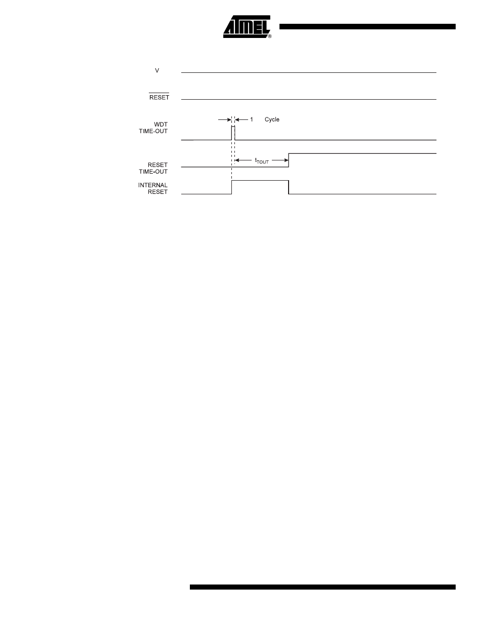
Figure 9-6.
Watchdog Reset During Operation
9.1
Internal Voltage Reference
ATtiny261/461/861 features an internal bandgap reference. This reference is used for Brown-out
Detection, and it can be used as an input to the Analog Comparator or the ADC.
9.1.1
Voltage Reference Enable Signals and Start-up Time
The voltage reference has a start-up time that may influence the way it should be used. The
start-up time is given in
”System and Reset Characteristics” on page 189
. To save power, the
reference is not always turned on. The reference is on during the following situations:
1.
When the BOD is enabled (by programming the BODLEVEL [2..0] Fuse).
2.
When the bandgap reference is connected to the Analog Comparator (by setting the
ACBG bit in ACSR).
3.
When the ADC is enabled.
Thus, when the BOD is not enabled, after setting the ACBG bit or enabling the ADC, the user
must always allow the reference to start up before the output from the Analog Comparator or
ADC is used. To reduce power consumption in Power-down mode, the user can avoid the three
conditions above to ensure that the reference is turned off before entering Power-down mode.
9.2
Watchdog Timer
The Watchdog Timer is clocked from an On-chip Oscillator which runs at 128 kHz. By controlling
the Watchdog Timer prescaler, the Watchdog Reset interval can be adjusted as shown in
Table
9-3 on page 46
. The WDR – Watchdog Reset – instruction resets the Watchdog Timer. The
Watchdog Timer is also reset when it is disabled and when a Chip Reset occurs. Ten different
clock cycle periods can be selected to determine the reset period. If the reset period expires
without another Watchdog Reset, the ATtiny261/461/861 resets and executes from the Reset
Vector. For timing details on the Watchdog Reset, refer to
Table 9-3 on page 46
.
The Wathdog Timer can also be configured to generate an interrupt instead of a reset. This can
be very helpful when using the Watchdog to wake-up from Power-down.
To prevent unintentional disabling of the Watchdog or unintentional change of time-out period,
two different safety levels are selected by the fuse WDTON as shown in Table 9-1. Refer to
”Timed Sequences for Changing the Configuration of the Watchdog Timer” on page 43
for
details.
CK
CC