3 power-on reset, 4 external reset – Rainbow Electronics ATtiny861_V User Manual
Page 40
40
2588B–AVR–11/06
ATtiny261/461/861
9.0.3
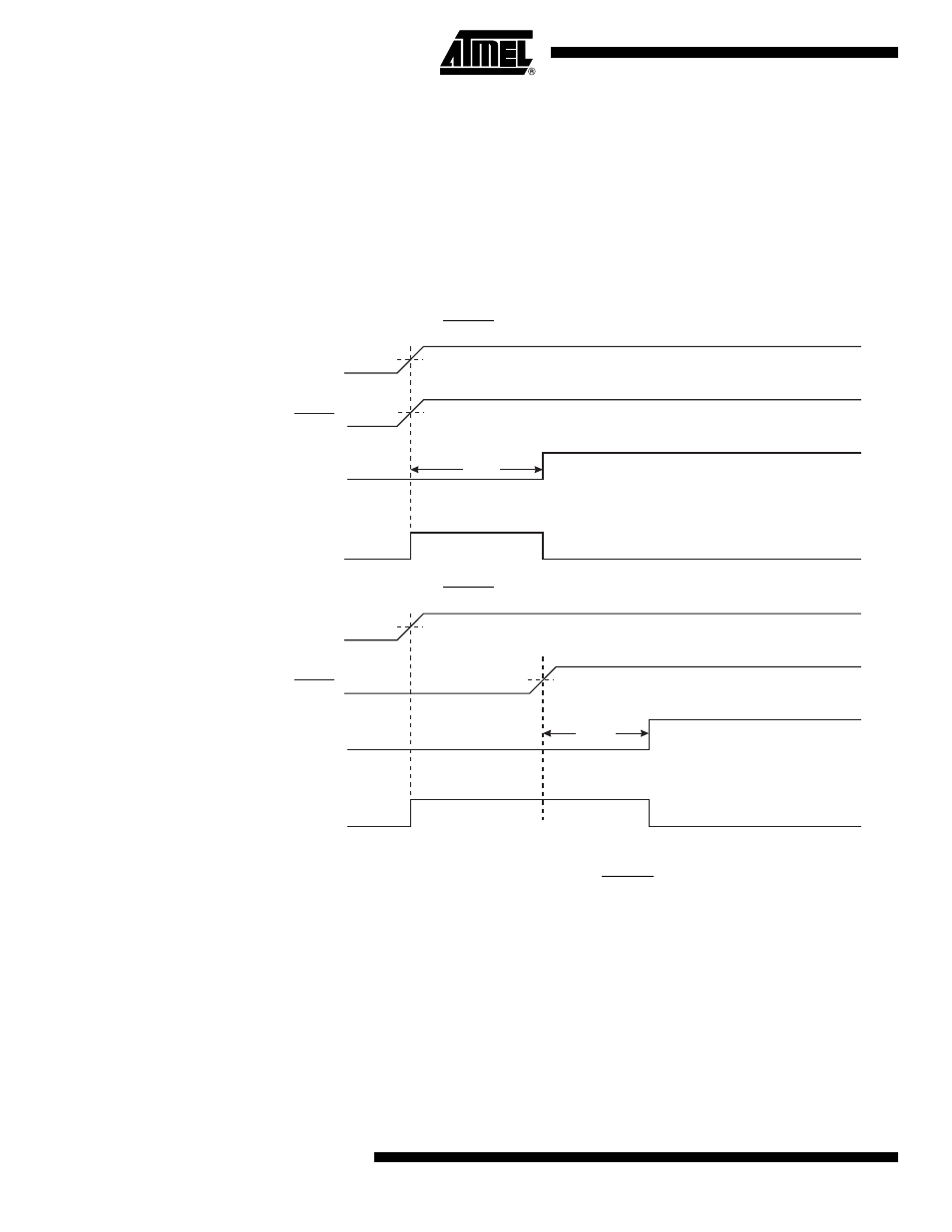
Power-on Reset
A Power-on Reset (POR) pulse is generated by an On-chip detection circuit. The detection level
is defined in
”System and Reset Characteristics” on page 189
. The POR is activated whenever
V
CC
is below the detection level. The POR circuit can be used to trigger the Start-up Reset, as
well as to detect a failure in supply voltage.
A Power-on Reset (POR) circuit ensures that the device is reset from Power-on. Reaching the
Power-on Reset threshold voltage invokes the delay counter, which determines how long the
device is kept in RESET after V
CC
rise. The RESET signal is activated again, without any delay,
when V
CC
decreases below the detection level.
Figure 9-2.
MCU Start-up, RESET Tied to V
CC
Figure 9-3.
MCU Start-up, RESET Extended Externally
9.0.4
External Reset
An External Reset is generated by a low level on the RESET pin if enabled. Reset pulses longer
than the minimum pulse width (see
”System and Reset Characteristics” on page 189
ate a reset, even if the clock is not running. Shorter pulses are not guaranteed to generate a
reset. When the applied signal reaches the Reset Threshold Voltage – V
RST
– on its positive
edge, the delay counter starts the MCU after the Time-out period – t
TOUT
–
has expired.
V
RESET
TIME-OUT
INTERNAL
RESET
t
TOUT
V
POT
V
RST
CC
RESET
TIME-OUT
INTERNAL
RESET
t
TOUT
V
POT
V
RST
V
CC