Rainbow Electronics ATtiny861_V User Manual
Page 30
30
2588B–AVR–11/06
ATtiny261/461/861
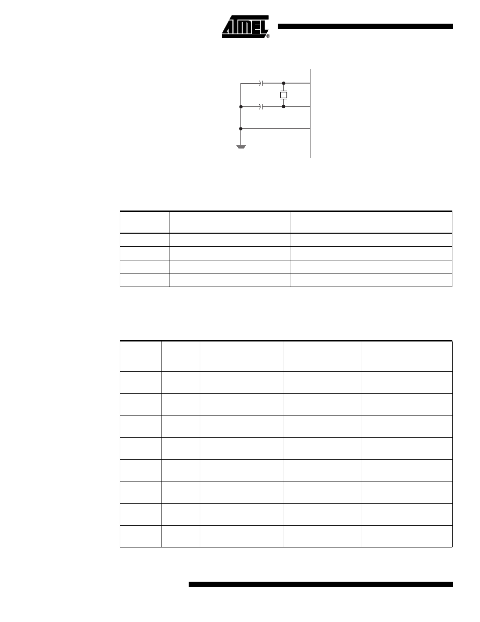
Figure 7-4.
Crystal Oscillator Connections
The Oscillator can operate in three different modes, each optimized for a specific frequency
range. The operating mode is selected by the fuses CKSEL3..1 as shown in
Table 7-10
.
Notes:
1. This option should not be used with crystals, only with ceramic resonators.
The CKSEL0 Fuse together with the SUT1..0 Fuses select the start-up times as shown in
Table
7-11
.
Table 7-10.
Crystal Oscillator Operating Modes
CKSEL3..1
Frequency Range (MHz)
Recommended Range for Capacitors C1 and
C2 for Use with Crystals (pF)
100
(1)
0.4 - 0.9
–
101
0.9 - 3.0
12 - 22
110
3.0 - 8.0
12 - 22
111
8.0 -
12 - 22
Table 7-11.
Start-up Times for the Crystal Oscillator Clock Selection
CKSEL0
SUT1..0
Start-up Time from
Power-down and
Power-save
Additional Delay
from Reset
(V
CC
= 5.0V)
Recommended Usage
0
00
258 CK
(1)
14CK + 4.1 ms
Ceramic resonator, fast
rising power
0
01
258 CK
(1)
14CK + 65 ms
Ceramic resonator, slowly
rising power
0
10
1K (1024) CK
(2)
14CK
Ceramic resonator, BOD
enabled
0
11
1K (1024)CK
(2)
14CK + 4.1 ms
Ceramic resonator, fast
rising power
1
00
1K (1024)CK
(2)
14CK + 65 ms
Ceramic resonator, slowly
rising power
1
01
16K (16384) CK
14CK
Crystal Oscillator, BOD
enabled
1
10
16K (16384) CK
14CK + 4.1 ms
Crystal Oscillator, fast
rising power
1
11
16K (16384) CK
14CK + 65 ms
Crystal Oscillator, slowly
rising power
XTAL2
XTAL1
GND
C2
C1