Example, 4 power-down supply current, Figure 24-11. power-down supply current vs. v – Rainbow Electronics ATtiny861_V User Manual
Page 201: Watchdog timer enabled)
201
2588B–AVR–11/06
ATtiny261/461/861
Example
Calculate the expected current consumption in idle mode with TIMER0, ADC, and USI enabled
at V
CC
= 2.0V and F = 1MHz. From
Table 24-2
, third column, we see that we need to add 10%
for the TIMER0, 27.3 % for the ADC, and 6.5 % for the USI module. Reading from
, we find that the idle current consumption is ~0,085 mA at V
CC
= 2.0V and F=1MHz.
The total current consumption in idle mode with TIMER0, ADC, and USI enabled, gives:
24.4
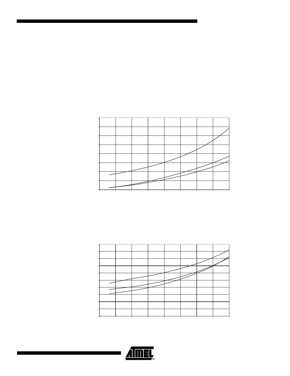
Power-down Supply Current
Figure 24-11. Power-down Supply Current vs. V
CC
(Watchdog Timer Disabled)
Figure 24-12. Power-down Supply Current vs. V
CC
(Watchdog Timer Enabled)
I
CC
total
0,085mA
1
0,10
0,273
0,065
+
+
+
(
)
•
0,122mA
≈
≈
POWER-DOWN SUPPLY CURRENT vs. V
CC
WATCHDOG TIMER DISABLED
85 ˚C
25 ˚C
-40 ˚C
0
0,2
0,4
0,6
0,8
1
1,2
1,4
1,6
1,5
2
2,5
3
3,5
4
4,5
5
5,5
V
CC
(V)
I
CC
(uA)
POWER-DOWN SUPPLY CURRENT vs. V
CC
WATCHDOG TIMER ENABLED
85 ˚C
25 ˚C
-40 ˚C
0
1
2
3
4
5
6
7
8
9
10
1,5
2
2,5
3
3,5
4
4,5
5
5,5
V
CC
(V)
I
CC
(uA)