System clock and clock options, 1 clock systems and their distribution, 1 cpu clock - clkcpu – Rainbow Electronics ATtiny861_V User Manual
Page 24: 2 i/o clock - clki/o, 3 flash clock - clkflash, 4 adc clock - clkadc
24
2588B–AVR–11/06
ATtiny261/461/861
7.
System Clock and Clock Options
7.1
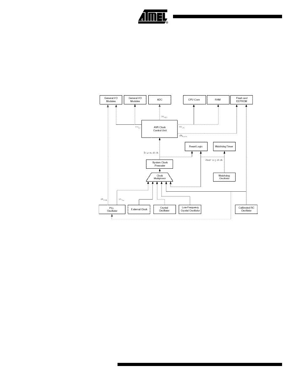
Clock Systems and their Distribution
Figure 7-1
presents the principal clock systems in the AVR and their distribution. All of the clocks
need not be active at a given time. In order to reduce power consumption, the clocks to modules
not being used can be halted by using different sleep modes, as described in
ment and Sleep Modes” on page 34
. The clock systems are detailed below.
Figure 7-1.
Clock Distribution
7.1.1
CPU Clock – clk
CPU
The CPU clock is routed to parts of the system concerned with operation of the AVR core.
Examples of such modules are the General Purpose Register File, the Status Register and the
Data memory holding the Stack Pointer. Halting the CPU clock inhibits the core from performing
general operations and calculations.
7.1.2
I/O Clock – clk
I/O
The I/O clock is used by the majority of the I/O modules, like Timer/Counter. The I/O clock is
also used by the External Interrupt module, but note that some external interrupts are detected
by asynchronous logic, allowing such interrupts to be detected even if the I/O clock is halted.
7.1.3
Flash Clock – clk
FLASH
The Flash clock controls operation of the Flash interface. The Flash clock is usually active simul-
taneously with the CPU clock.
7.1.4
ADC Clock – clk
ADC
The ADC is provided with a dedicated clock domain. This allows halting the CPU and I/O clocks
in order to reduce noise generated by digital circuitry. This gives more accurate ADC conversion
results.