3 tccr1c - timer/counter1 control register c – Rainbow Electronics ATtiny861_V User Manual
Page 117
117
2588B–AVR–11/06
ATtiny261/461/861
• Bits 3 .. 0 - CS13, CS12, CS11, CS10: Clock Select Bits 3, 2, 1, and 0
The Clock Select bits 3, 2, 1, and 0 define the prescaling source of Timer/Counter1.
The Stop condition provides a Timer Enable/Disable function.
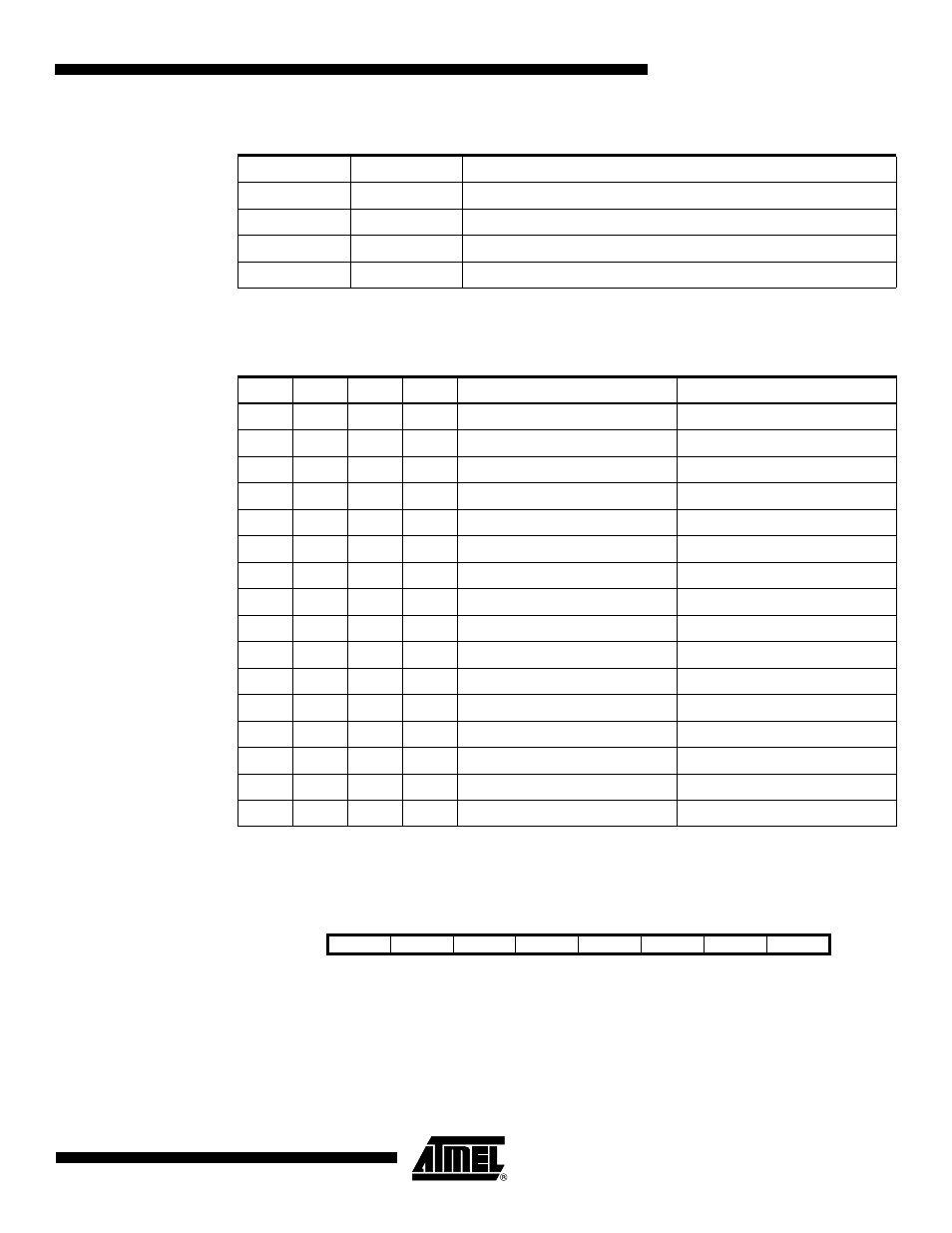
16.11.3
TCCR1C – Timer/Counter1 Control Register C
• Bits 7,6 - COM1A1S, COM1A0S: Comparator A Output Mode, Bits 1 and 0
These bits are the shadow bits of the COM1A1 and COM1A0 bits that are described in the sec-
tion
”TCCR1A – Timer/Counter1 Control Register A” on page 113
Table 16-14. Division factors of the Dead Time prescaler
DTPS11
DTPS10
Prescaler divides the T/C1 clock by
0
0
1x (no division)
0
1
2x
1
0
4x
1
1
8x
Table 16-15. Timer/Counter1 Prescaler Select
CS13
CS12
CS11
CS10
Asynchronous Clocking Mode
Synchronous Clocking Mode
0
0
0
0
T/C1 stopped
T/C1 stopped
0
0
0
1
PCK
CK
0
0
1
0
PCK/2
CK/2
0
0
1
1
PCK/4
CK/4
0
1
0
0
PCK/8
CK/8
0
1
0
1
PCK/16
CK/16
0
1
1
0
PCK/32
CK/32
0
1
1
1
PCK/64
CK/64
1
0
0
0
PCK/128
CK/128
1
0
0
1
PCK/256
CK/256
1
0
1
0
PCK/512
CK/512
1
0
1
1
PCK/1024
CK/1024
1
1
0
0
PCK/2048
CK/2048
1
1
0
1
PCK/4096
CK/4096
1
1
1
0
PCK/8192
CK/8192
1
1
1
1
PCK/16384
CK/16384
Bit
7
6
5
4
3
2
1
0
0x27 (0x47)
COM1A1S
COM1A0S
COM1B1S
COM1B0S
COM1D1
COM1D0
FOC1D
PWM1D
TCCR1C
Read/Write
R/W
R/W
R/W
R/W
R/W
R/W
R/W
R/W
Initial value
0
0
0
0
0
0
0
0