1 register description, 1 pllcsr - pll control and status register, 2 tccr1b - timer/counter1 control register b – Rainbow Electronics ATtiny861_V User Manual
Page 89
89
2588B–AVR–11/06
ATtiny261/461/861
15.1
Register Description
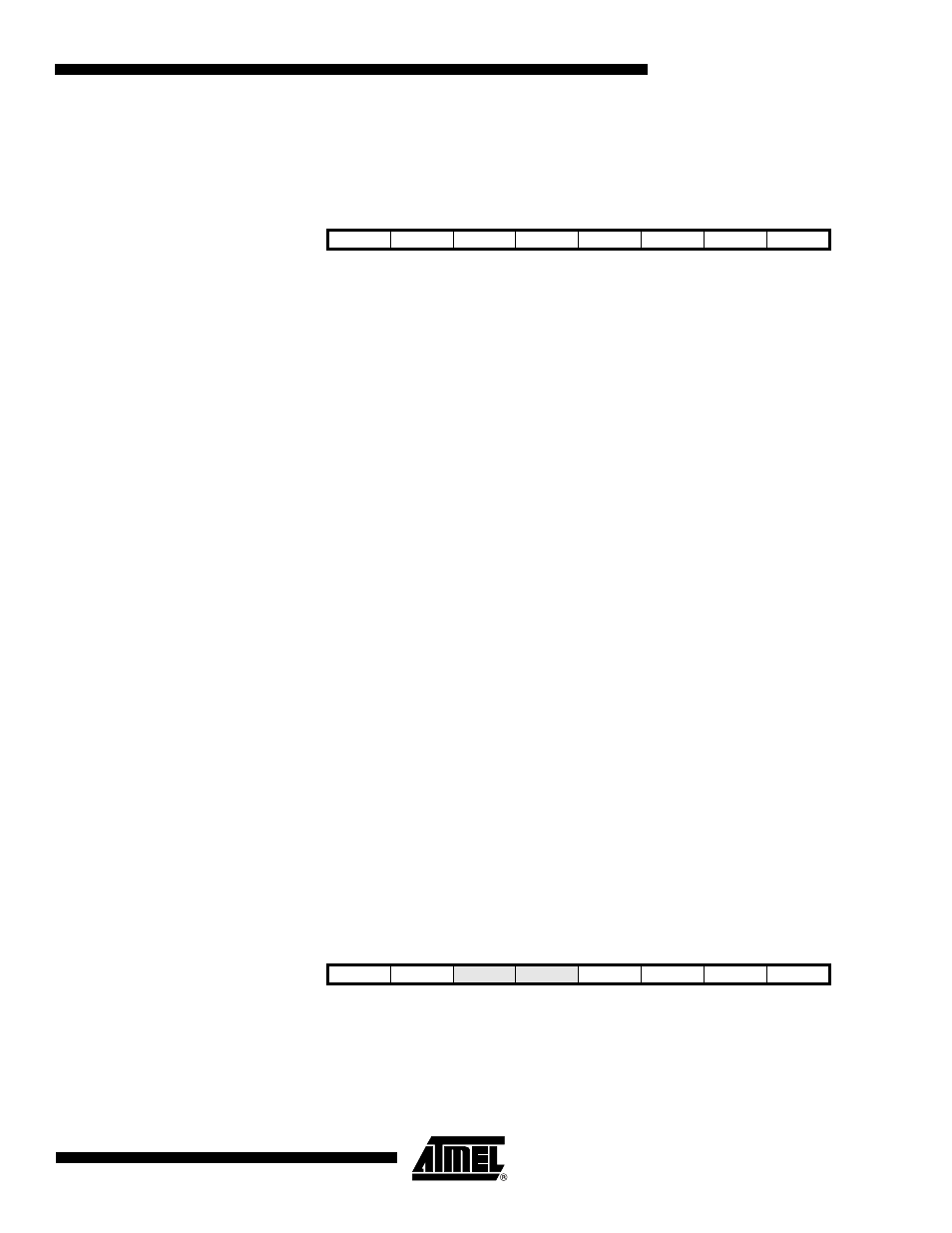
15.1.1
PLLCSR – PLL Control and Status Register
• Bit 7- LSM: Low Speed Mode
The Low Speed mode is selected, if the LSM bit is written to one, and then the fast peripheral
clock is scaled down from 64 MHz to 32 MHz. As default the LSM bit is reset to zero, the Low
Speed Mode is disabled and the fast peripheral clock is 64 MHz. The Low Speed Mode must be
set, if the supply voltage is below 2.7 volts, because the Timer/Counter1 is not running fast
enough on low voltage levels. It is recommended that the Timer/Counter1 is stopped whenever
the LSM bit is written.
• Bit 6:3- Res : Reserved Bits
These bits are reserved bits in the ATtiny261/461/861 and always read as zero.
• Bit 2- PCKE: PCK Enable
The PCKE bit change the Timer/Counter1 clock source. When it is set, the asynchronous clock
mode is enabled and fast 64 MHz (or 32 MHz in Low Speed Mode) PCK clock is used as a
Timer/Counter1 clock source. If this bit is cleared, the synchronous clock mode is enabled, and
system clock CK is used as Timer/Counter1 clock source. It is safe to set this bit only when the
PLL is locked i.e the PLOCK bit is 1. Note that the PCKE bit can be set only, if the PLL has been
enabled earlier. The PLL is enabled when the CKSEL fuses have been programmed to 0x0001
(the PLL clock mode is selected) or the PLLE bit has been set to one.
• Bit 1- PLLE: PLL Enable
When the PLLE is set, the PLL is started and if needed internal RC-oscillator is started as a PLL
reference clock. If PLL is selected as a system clock source the value for this bit is always 1.
• Bit 0- PLOCK: PLL Lock Detector
When the PLOCK bit is set, the PLL is locked to the reference clock. The PLOCK bit should be
ignored during initial PLL lock-in sequence when PLL frequency overshoots and undershoots,
before reaching steady state. The steady state is obtained within 100 µs. After PLL lock-in it is
recommended to check the PLOCK bit before enabling PCK for Timer/Counter1.
15.1.2
TCCR1B – Timer/Counter1 Control Register B
• Bit 7 - Res: Reserved Bit
• Bit 6 - PSR1 : Prescaler Reset Timer/Counter1
Bit
7
6
5
4
3
2
1
0
0x29 (0x49)
LSM
-
-
-
-
PCKE
PLLE
PLOCK
PLLCSR
Read/Write
R/W
R
R
R
R
R/W
R/W
R
Initial value
0
0
0
0
0
0
0/1
0
Bit
7
6
5
4
3
2
1
0
0x2F (0x4F)
-
PSR1
DTPS11
DTPS10
CS13
CS12
CS11
CS10
TCCR1B
Read/Write
R/W
R/W
R/W
R/W
R/W
R/W
R/W
R/W
Initial value
0
0
0
0
0
0
0
0