5 system and reset characteristics, Logic, System and reset character – Rainbow Electronics ATtiny861_V User Manual
Page 189: Up time is given in
189
2588B–AVR–11/06
ATtiny261/461/861
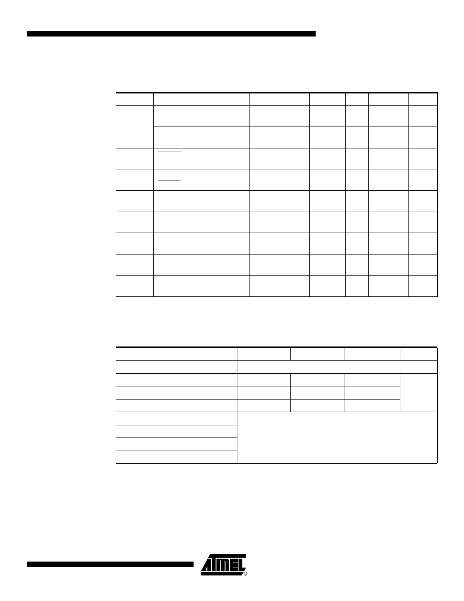
23.5
System and Reset Characteristics
Notes:
1. Values are guidelines only. Actual values are TBD.
2. The Power-on Reset will not work unless the supply voltage has been below V
POT
(falling)
Note:
1. V
BOT
may be below nominal minimum operating voltage for some devices. For devices where
this is the case, the device is tested down to V
CC
= V
BOT
during the production test. This guar-
antees that a Brown-out Reset will occur before V
CC
drops to a voltage where correct
operation of the microcontroller is no longer guaranteed.
Table 23-3.
Reset, Brown-out and Internal Voltage Characteristics
(1)
Symbol
Parameter
Condition
Min
Typ
Max
Units
V
POT
Power-on Reset Threshold
Voltage (rising)
T
A
= -40 - 85
°C
0.7
1.0
1.4
V
Power-on Reset Threshold
Voltage (falling)
(2)
T
A
= -40 - 85
°C
0.6
0.9
1.3
V
V
RST
RESET Pin Threshold
Voltage
V
CC
= 3V
0.2 V
CC
0.9 V
CC
V
t
RST
Minimum pulse width on
RESET Pin
V
CC
= 3V
2.5
µs
V
HYST
Brown-out Detector
Hysteresis
50
mV
t
BOD
Min Pulse Width on Brown-
out Reset
2
µs
V
BG
Bandgap reference voltage
V
CC
= 2.7V,
T
A
= 25°C
1.0
1.1
1.2
V
t
BG
Bandgap reference start-up
time
V
CC
= 2.7V,
T
A
= 25°C
40
70
µs
I
BG
Bandgap reference current
consumption
V
CC
= 2.7V,
T
A
= 25°C
15
µA
Table 23-4.
BODLEVEL Fuse Coding
(1)
BODLEVEL [2..0] Fuses
Min V
BOT
Typ V
BOT
Max V
BOT
Units
111
BOD Disabled
110
1.7
1.8
2.0
V
101
2.5
2.7
2.9
100
4.1
4.3
4.5
011
Reserved
010
001
000