3 supply current of i/o modules – Rainbow Electronics ATtiny861_V User Manual
Page 200
200
2588B–AVR–11/06
ATtiny261/461/861
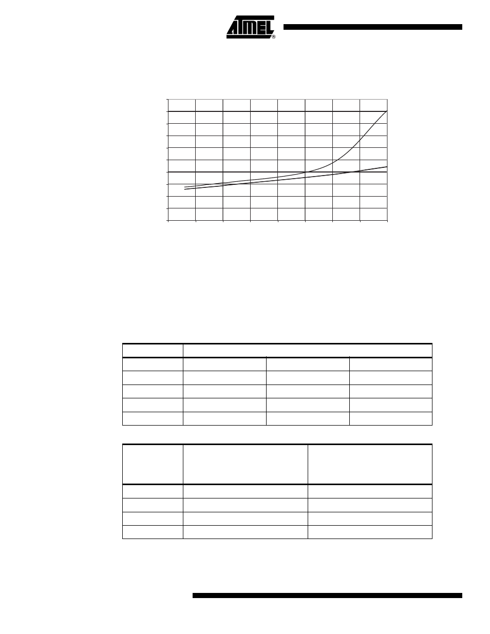
Figure 24-10. Idle Supply Current vs. V
CC
(Internal RC Oscillator, 128 kHz)
24.3
Supply Current of I/O modules
The tables and formulas below can be used to calculate the additional current consumption for
the different I/O modules in Active and Idle mode. The enabling or disabling of the I/O modules
are controlled by the Power Reduction Register. See
”PRR – Power Reduction Register” on
for details.
It is possible to calculate the typical current consumption based on the numbers from
Table 24-1
for other V
CC
and frequency settings than listed in
Table 24-2
.
IDLE SUPPLY CURRENT vs. V
CC
INTERNAL RC OSCILLATOR, 128 kHz
85 ˚C
25 ˚C
-40 ˚C
0
0,02
0,04
0,06
0,08
0,1
0,12
0,14
0,16
0,18
0,2
1,5
2
2,5
3
3,5
4
4,5
5
5,5
V
CC
(V)
I
CC
(mA)
Table 24-1.
Additional Current Consumption for the different I/O modules (absolute values)
PRR bit
Typical numbers
V
CC
= 2V, F = 1MHz
V
CC
= 3V, F = 4MHz
V
CC
= 5V, F = 8MHz
PRTIM1
65 uA
423 uA
1787 uA
PRTIM0
7 uA
39 uA
165 uA
PRUSI
5 uA
25 uA
457 uA
PRADC
18 uA
111 uA
102 uA
Table 24-2.
Additional Current Consumption (percentage) in Active and Idle mode
PRR bit
Additional Current consumption
compared to Active with external
clock (see
)
Additional Current consumption
compared to Idle with external
clock (see
PRTIM1
26.9 %
103.7 %
PRTIM0
2.6 %
10.0 %
PRUSI
1.7 %
6.5 %
PRADC
7.1 %
27.3 %