2 fuse bytes – Rainbow Electronics ATtiny861_V User Manual
Page 169
169
2588B–AVR–11/06
ATtiny261/461/861
22.2
Fuse Bytes
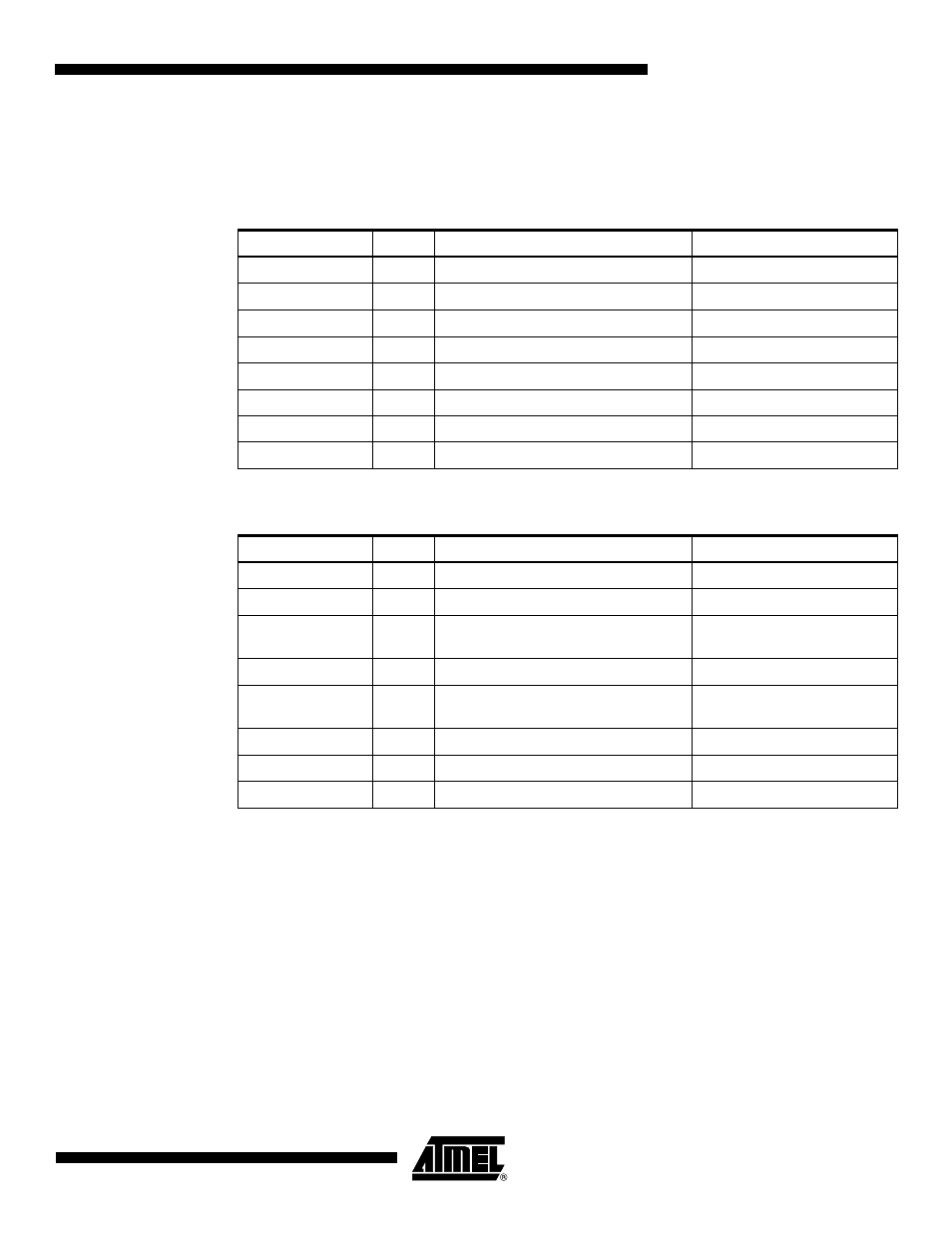
The ATtiny261/461/861 has three Fuse bytes.
,
Table 22-4
and
Table 22-5
describe
briefly the functionality of all the fuses and how they are mapped into the Fuse bytes. Note that
the fuses are read as logical zero, “0”, if they are programmed.
Notes:
1. See
”Alternate Functions of Port B” on page 61
for description of RSTDISBL and DWEN
Fuses.
2. DWEN must be unprogrammed when Lock Bit security is required.
3. The SPIEN Fuse is not accessible in SPI Programming mode.
4. See
”WDTCR – Watchdog Timer Control Register” on page 44
for details.
5. See
Table 23-4 on page 189
for BODLEVEL Fuse decoding.
6. When programming the RSTDISBL Fuse, High-voltage Serial programming has to be used to
change fuses to perform further programming.
Table 22-3.
Fuse Extended Byte
Fuse High Byte
Bit No
Description
Default Value
7
-
1 (unprogrammed)
6
-
1 (unprogrammed)
5
-
1 (unprogrammed)
4
-
1 (unprogrammed)
3
-
1 (unprogrammed)
2
-
1 (unprogrammed)
1
-
1 (unprogrammed)
SELFPRGEN
0
Self-Programming Enable
1 (unprogrammed)
Table 22-4.
Fuse High Byte
Fuse High Byte
Bit No
Description
Default Value
RSTDISBL
(1)
7
External Reset disable
1 (unprogrammed)
DWEN
(2)
6
DebugWIRE Enable
1 (unprogrammed)
SPIEN
(3)
6
Enable Serial Program and Data
Downloading
0 (programmed, SPI prog.
enabled)
WDTON
(4)
4
Watchdog Timer always on
1 (unprogrammed)
EESAVE
3
EEPROM memory is preserved
through the Chip Erase
1 (unprogrammed, EEPROM
not preserved)
BODLEVEL2
(5)
2
Brown-out Detector trigger level
1 (unprogrammed)
BODLEVEL1
(5)
1
Brown-out Detector trigger level
1 (unprogrammed)
BODLEVEL0
(5)
0
Brown-out Detector trigger level
1 (unprogrammed)