4 watchdog reset, 5 mcu status register - mcusr, Figure – Rainbow Electronics ATmega64C1 User Manual
Page 48: Figure 7-5
48
7647A–AVR–02/08
ATmega32/64/M1/C1
Figure 7-5.
Brown-out Reset During Operation
7.2.4
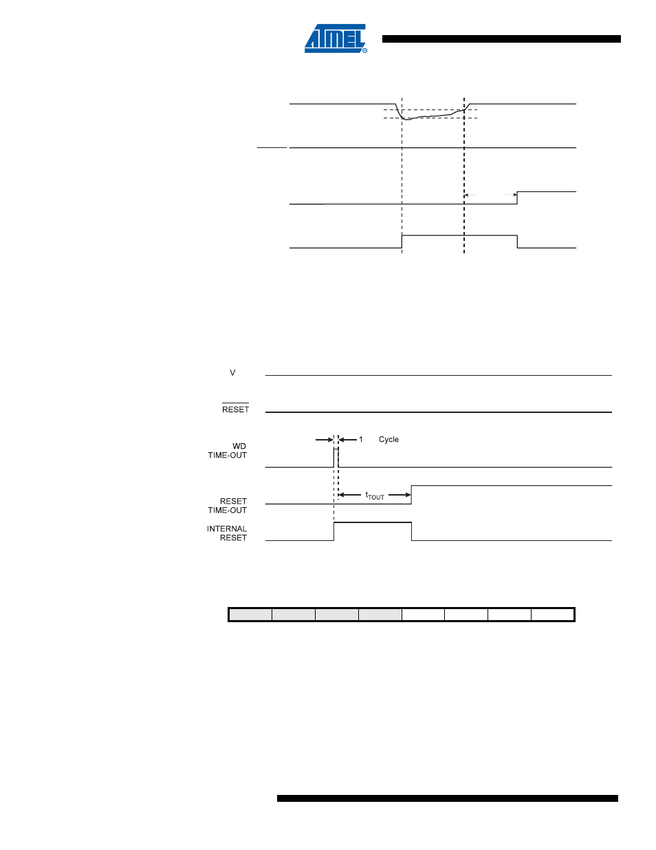
Watchdog Reset
When the Watchdog times out, it will generate a short reset pulse of one CK cycle duration. On
the falling edge of this pulse, the delay timer starts counting the Time-out period t
TOUT
. Refer to
for details on operation of the Watchdog Timer.
Figure 7-6.
Watchdog Reset During Operation
7.2.5
MCU Status Register – MCUSR
The MCU Status Register provides information on which reset source caused an MCU reset.
• Bit 3 – WDRF: Watchdog Reset Flag
This bit is set if a Watchdog Reset occurs. The bit is reset by a Power-on Reset, or by writing a
logic zero to the flag.
• Bit 2 – BORF: Brown-out Reset Flag
This bit is set if a Brown-out Reset occurs. The bit is reset by a Power-on Reset, or by writing a
logic zero to the flag.
• Bit 1 – EXTRF: External Reset Flag
V
CC
RESET
TIME-OUT
INTERNAL
RESET
V
BOT-
V
BOT+
t
TOUT
CK
CC
Bit
7
6
5
4
3
2
1
0
–
–
–
–
WDRF
BORF
EXTRF
PORF
MCUSR
Read/Write
R
R
R
R
R/W
R/W
R/W
R/W
Initial Value
0
0
0
0
See Bit Description