8 psc control register - pctl, Pccyc = 1) – Rainbow Electronics ATmega64C1 User Manual
Page 153
153
7647A–AVR–02/08
ATmega32/64/M1/C1
• Bit 3 – POPB: PSC B Output Polarity
If this bit is cleared, the PSC outputs B are active Low.
If this bit is set, the PSC outputs B are active High.
• Bit 2 – POPA: PSC A Output Polarity
If this bit is cleared, the PSC outputs A are active Low.
If this bit is set, the PSC outputs A are active High.
• Bit 1:0 – not use
not use
14.16.8
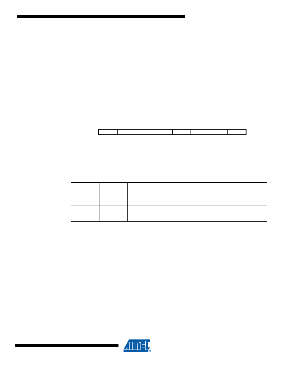
PSC Control Register – PCTL
• Bit 7:6 – PPRE1:0 : PSC Prescaler Select
This two bits select the PSC input clock division factor. All generated waveform will be modified
by this factor.
• Bit 5 – PCLKSEL: PSC Input Clock Select
This bit is used to select between CLK
PLL
or CLK
IO
clocks.
Set this bit to select the fast clock input (CLK
PLL
).
Clear this bit to select the slow clock input (CLK
IO
).
• Bit 4:2 – not use
not use
• Bit 1 – PCCYC: PSC Complete Cycle
When this bit is set, the PSC completes the entire waveform cycle before halt operation
requested by clearing PRUN.
• Bit 0 – PRUN : PSC Run
Writing this bit to one starts the PSC.
Bit
7
6
5
4
3
2
1
0
PPRE1
PPRE0
PCLKSEL
-
-
-
PCCYC
PRUN
PCTL
Read/Write
R/W
R/W
R/W
R
R
R
R/W
R/W
Initial Value
0
0
0
0
0
0
0
0
Table 14-11. PSC Prescaler Selection
PPRE1
PPRE0
Description
0
0
No divider on PSC input clock
0
1
Divide the PSC input clock by 4
1
0
Divide the PSC input clock by 32
1
1
Divide the PSC clock by 256