Spi pin overrides – Rainbow Electronics ATmega64C1 User Manual
Page 159
159
7647A–AVR–02/08
ATmega32/64/M1/C1
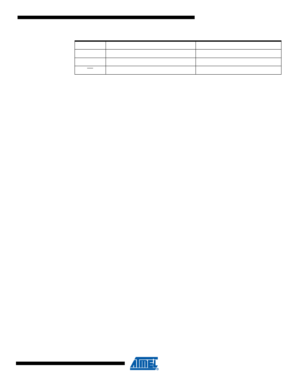
Note:
1. See
“Alternate Functions of Port B” on page 67
for a detailed description of how to define the
direction of the user defined SPI pins.
The following code examples show how to initialize the SPI as a Master and how to perform a
simple transmission.
DDR_SPI in the examples must be replaced by the actual Data Direction Register controlling the
SPI pins. DD_MOSI, DD_MISO and DD_SCK must be replaced by the actual data direction bits
for these pins. E.g. if MOSI is placed on pin PB2, replace DD_MOSI with DDB2 and DDR_SPI
with DDRB.
MISO
Input
User Defined
SCK
User Defined
Input
SS
User Defined
Input
Table 15-1.
SPI Pin Overrides
(1)
Pin
Direction, Master SPI
Direction, Slave SPI
See also other documents in the category Rainbow Electronics Sensors:
- MAX5151 (16 pages)
- MAXQ3108 (64 pages)
- MAX5661 (39 pages)
- MAX6691 (7 pages)
- MAX5362 (12 pages)
- ADC10158 (26 pages)
- MAX8922L (14 pages)
- MAX8596Z (8 pages)
- MAX7491 (18 pages)
- MAX15040 (15 pages)
- MAX5177 (16 pages)
- ADC08138 (22 pages)
- MAX5961 (42 pages)
- T89C51RD2 (86 pages)
- MAX16055 (9 pages)
- MAX6659 (17 pages)
- ADC0820 (20 pages)
- MAX6678 (19 pages)
- MAX8884Z (15 pages)
- MAX16915 (9 pages)
- MAX8620 (18 pages)
- MAX5144 (12 pages)
- MAX6670 (8 pages)
- MAX8760 (39 pages)
- W78C32C (14 pages)
- MX7533 (8 pages)
- MAX8727 (13 pages)
- MAX9053 (15 pages)
- W78C54 (16 pages)
- MAX8614B (15 pages)
- W90N740 (219 pages)
- MAX6626 (13 pages)
- ADC10738 (30 pages)
- MAX17000 (31 pages)
- MAX5051 (21 pages)
- MAXQ1004 (18 pages)
- MAX6871 (51 pages)
- MX7847 (12 pages)
- MAX6608 (6 pages)
- MAX17083 (15 pages)
- MAX6641 (17 pages)
- MAX5251 (16 pages)
- MAX6338 (8 pages)
- MAX6690 (16 pages)
- MAX8668 (18 pages)