5 can time stamp registers - canstml and canstmh, 6 can data message register - canmsg, 12 examples of can baud rate setting – Rainbow Electronics ATmega64C1 User Manual
Page 199
199
7647A–AVR–02/08
ATmega32/64/M1/C1
– 0 - comparison true forced
– 1 - bit comparison enabled.
16.11.5
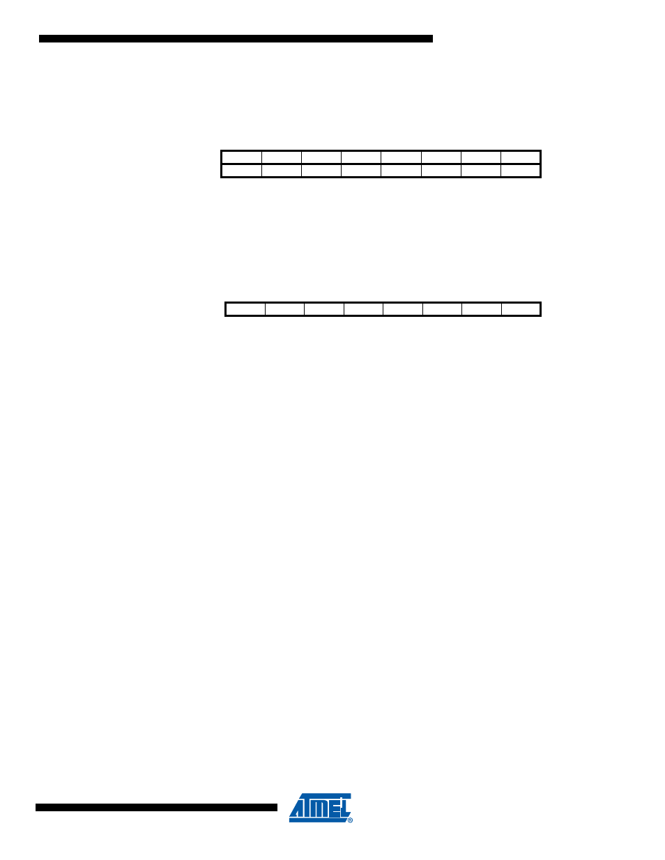
CAN Time Stamp Registers - CANSTML and CANSTMH
• Bits 15:0 - TIMSTM15:0: Time Stamp Count
CAN time stamp counter range 0 to 65,535.
16.11.6
CAN Data Message Register - CANMSG
• Bit 7:0 – MSG7:0: Message Data
This register contains the CAN data byte pointed at the page MOb register.
After writing in the page MOb register, this byte is equal to the specified message location of the
pre-defined identifier + index. If auto-incrementation is used, at the end of the data register writ-
ing or reading cycle, the index is auto-incremented.
The range of the counting is 8 with no end of loop (0, 1,..., 7, 0,...).
16.12 Examples of CAN Baud Rate Setting
The CAN bus requires very accurate timing especially for high baud rates. It is recommended to
use only an external crystal for CAN operations.
for timing description and
for “CAN Bit Timing Registers”).
Bit
7
6
5
4
3
2
1
0
TIMSTM7 TIMSTM6 TIMSTM5 TIMSTM4 TIMSTM3 TIMSTM2 TIMSTM1 TIMSTM0
CANSTML
TIMSTM15 TIMSTM14 TIMSTM13 TIMSTM12 TIMSTM11 TIMSTM10 TIMSTM9 TIMSTM8
CANSTMH
Bit
15
14
13
12
11
10
9
8
Read/Write
R
R
R
R
R
R
R
R
Initial Value
-
-
-
-
-
-
-
-
Bit
7
6
5
4
3
2
1
0
MSG 7
MSG 6
MSG 5
MSG 4
MSG 3
MSG 2
MSG 1
MSG 0
CANMSG
Read/Write
R/W
R/W
R/W
R/W
R/W
R/W
R/W
R/W
Initial Value
-
-
-
-
-
-
-
-