Figure 18-14 – Rainbow Electronics ATmega64C1 User Manual
Page 239
239
7647A–AVR–02/08
ATmega32/64/M1/C1
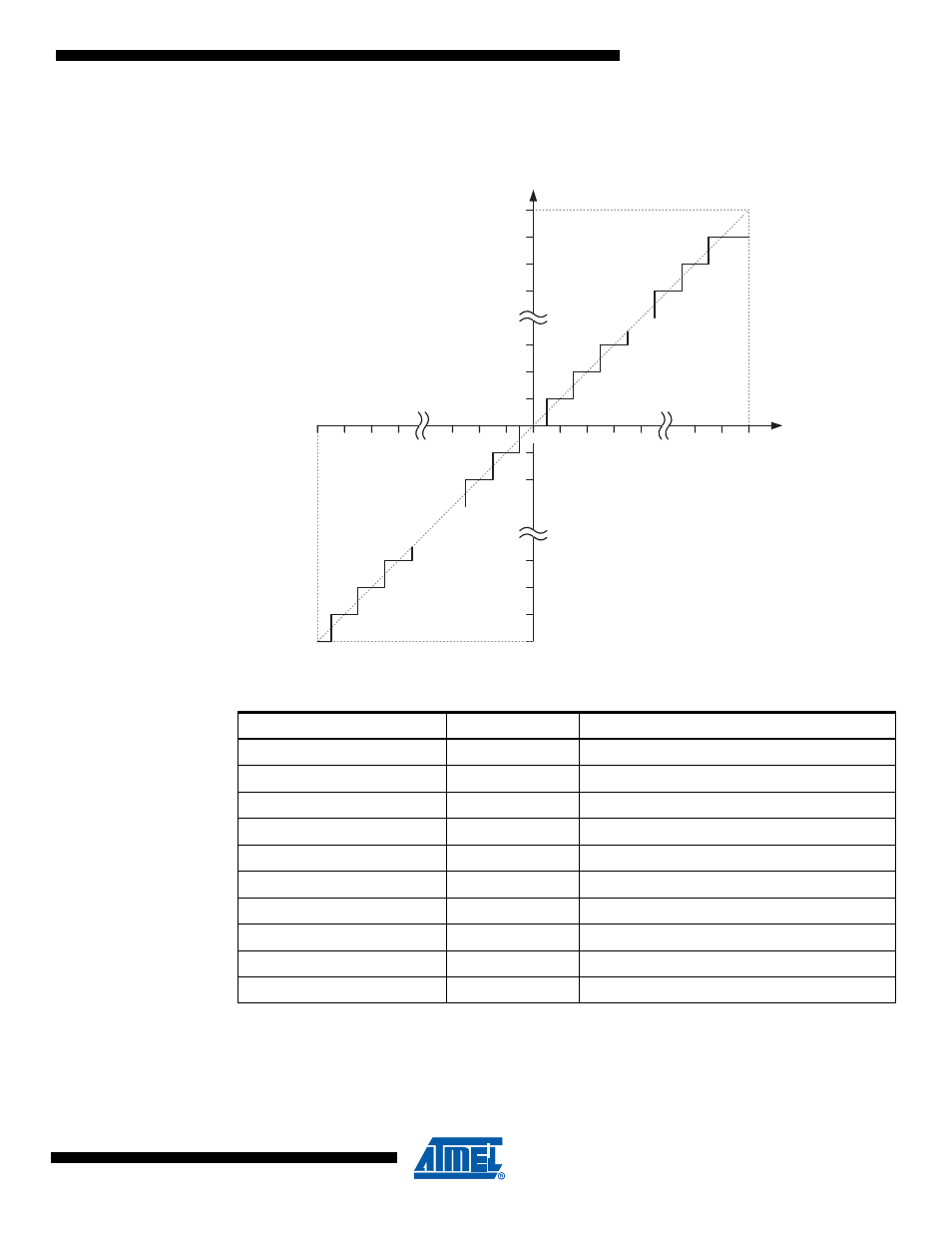
Table 82
shows the resulting output codes if the differential input channel pair (ADCn - ADCm) is
selected with a reference voltage of V
REF
.
Figure 18-14. Differential Measurement Range
Example 1:
–
ADMUX = 0xED (ADC3 - ADC2, 10x gain, 2.56V reference, left adjusted result)
–
Voltage on ADC3 is 300 mV, voltage on ADC2 is 500 mV.
–
ADCR = 512 * 10 * (300 - 500) / 2560 = -400 = 0x270
Table 18-2.
Correlation Between Input Voltage and Output Codes
V
ADCn
Read code
Corresponding decimal value
V
ADCm
+ V
REF
/GAIN
0x1FF
511
V
ADCm
+ 0.999 V
REF
/GAIN
0x1FF
511
V
ADCm
+ 0.998 V
REF
/GAIN
0x1FE
510
...
...
...
V
ADCm
+ 0.001 V
REF
/GAIN
0x001
1
V
ADCm
0x000
0
V
ADCm
- 0.001 V
REF
/GAIN
0x3FF
-1
...
...
...
V
ADCm
- 0.999 V
REF
/GAIN
0x201
-511
V
ADCm
- V
REF
/GAIN
0x200
-512
0
Output Code
0x1FF
0x000
V
REF
Differential Input
Voltage (Volts)
0x3FF
0x200
- V
REF
/Gain
/Gain
- MAX5151 (16 pages)
- MAXQ3108 (64 pages)
- MAX5661 (39 pages)
- MAX6691 (7 pages)
- MAX5362 (12 pages)
- ADC10158 (26 pages)
- MAX8922L (14 pages)
- MAX8596Z (8 pages)
- MAX7491 (18 pages)
- MAX15040 (15 pages)
- MAX5177 (16 pages)
- ADC08138 (22 pages)
- MAX5961 (42 pages)
- T89C51RD2 (86 pages)
- MAX16055 (9 pages)
- MAX6659 (17 pages)
- ADC0820 (20 pages)
- MAX6678 (19 pages)
- MAX8884Z (15 pages)
- MAX16915 (9 pages)
- MAX8620 (18 pages)
- MAX5144 (12 pages)
- MAX6670 (8 pages)
- MAX8760 (39 pages)
- W78C32C (14 pages)
- MX7533 (8 pages)
- MAX8727 (13 pages)
- MAX9053 (15 pages)
- W78C54 (16 pages)
- MAX8614B (15 pages)
- W90N740 (219 pages)
- MAX6626 (13 pages)
- ADC10738 (30 pages)
- MAX17000 (31 pages)
- MAX5051 (21 pages)
- MAXQ1004 (18 pages)
- MAX6871 (51 pages)
- MX7847 (12 pages)
- MAX6608 (6 pages)
- MAX17083 (15 pages)
- MAX6641 (17 pages)
- MAX5251 (16 pages)
- MAX6338 (8 pages)
- MAX6690 (16 pages)
- MAX8668 (18 pages)