6 power reduction register, 1 power reduction register - prr – Rainbow Electronics ATmega64C1 User Manual
Page 41
41
7647A–AVR–02/08
ATmega32/64/M1/C1
with the exception that the Oscillator is kept running. From Standby mode, the device wakes up
in six clock cycles.
Notes:
1. Only recommended with external crystal or resonator selected as clock source.
2. Only level interrupt.
6.6
Power Reduction Register
The Power Reduction Register, PRR, provides a method to stop the clock to individual peripher-
als to reduce power consumption. The current state of the peripheral is frozen and the I/O
registers can not be read or written. Resources used by the peripheral when stopping the clock
will remain occupied, hence the peripheral should in most cases be disabled before stopping the
clock. Waking up a module, which is done by clearing the bit in PRR, puts the module in the
same state as before shutdown.
A full predictible behaviour of a peripheral
is not guaranteed during and after a cycle of stopping
and starting of its clock. So its recommended to stop a peripheral before stopping its clock with
PRR register.
Module shutdown can be used in Idle mode and Active mode to significantly reduce the overall
power consumption. In all other sleep modes, the clock is already stopped.
6.6.1
Power Reduction Register - PRR
• Bit 7 -
Res: Reserved Bit
This bit is unused bit in the ATmega32/64/M1/C1, and will always read as zero.
• Bit 6 - PRCAN: Power Reduction CAN
Writing a logic one to this bit reduces the consumption of the CAN by stopping the clock to this
module. When waking up the CAN again, the CAN should be re initialized to ensure proper
operation.
• Bit 5 - PRPSC: Power Reduction PSC
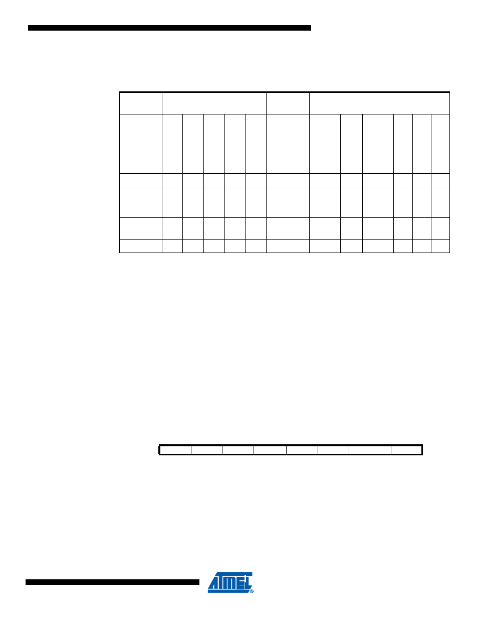
Table 6-2.
Active Clock Domains and Wake-up Sources in the Different Sleep Modes.
Active Clock Domains
Oscillator
s
Wake-up Sources
Sleep
Mode
clk
CPU
clk
FLASH
clk
IO
clk
ADC
clk
PLL
Ma
in Clo
c
k
Sour
ce Enab
led
INT
3
..0
PSC
SPM/EEPR
OM
Rea
d
y
ADC
WDT
Ot
herI/
O
Idle
X
X
X
X
X
X
X
X
X
X
ADC
Noise
Reduction
X
X
X
X
X
X
X
Power-
down
X
Standby
X
X
Bit
7
6
5
4
3
2
1
0
-
PRCAN
PRPSC
PRTIM1
PRTIM0
PRSPI
PRLIN
PRADC
PRR
Read/Write
R
R/W
R/W
R/W
R/W
R/W
R/W
R/W
Initial Value
0
0
0
0
0
0
0
0