4 psc description, Figure 14-1. power stage controller block diagram – Rainbow Electronics ATmega64C1 User Manual
Page 135
135
7647A–AVR–02/08
ATmega32/64/M1/C1
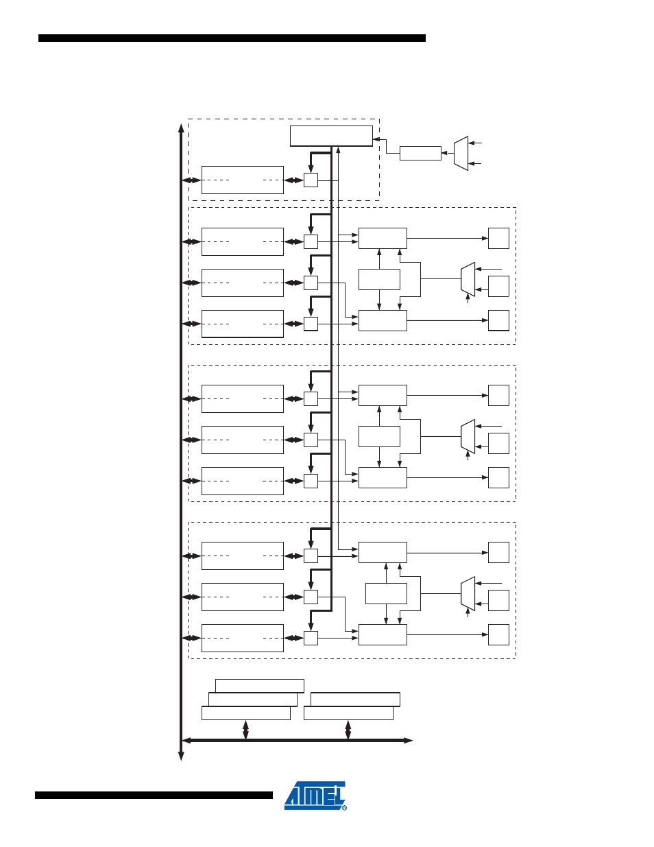
14.4
PSC Description
Figure 14-1. Power Stage Controller Block Diagram
DATABUS
POCR_RB
=
PSC Counter
Waveform
Generator B
PSCOUT0B
PCTLn
PFRCnA
PSOCn
(Analog Comparator 1 Ouput)
PCNFn
PFRCnB
PSCIN1
PISEL1
PSC Input 1
POCR0SB
=
POCR0RA
=
POCR0SA
=
Waveform
Generator A
PSCOUT0A
Waveform
Generator B
PSCOUT1B
POCR1SB
=
POCR1RA
=
POCR1SA
=
Waveform
Generator A
PSCOUT1A
Waveform
Generator B
PSCOUT2B
POCR2SB
=
POCR2RA
=
POCR2SA
=
Waveform
Generator A
PSCOUT2A
module 0
module 1
module 2
Overlap
Protection
Overlap
Protection
Overlap
Protection
(Analog Comparator 0 Ouput)
PSCIN0
PISEL0
PSC Input 0
(Analog Comparator 2 Ouput)
PSCIN2
PISEL2
PSC Input 2
AC0O
AC1O
AC2O
Prescaler
CLK
IO
CLK
PLL
See also other documents in the category Rainbow Electronics Sensors:
- MAX5151 (16 pages)
- MAXQ3108 (64 pages)
- MAX5661 (39 pages)
- MAX6691 (7 pages)
- MAX5362 (12 pages)
- ADC10158 (26 pages)
- MAX8922L (14 pages)
- MAX8596Z (8 pages)
- MAX7491 (18 pages)
- MAX15040 (15 pages)
- MAX5177 (16 pages)
- ADC08138 (22 pages)
- MAX5961 (42 pages)
- T89C51RD2 (86 pages)
- MAX16055 (9 pages)
- MAX6659 (17 pages)
- ADC0820 (20 pages)
- MAX6678 (19 pages)
- MAX8884Z (15 pages)
- MAX16915 (9 pages)
- MAX8620 (18 pages)
- MAX5144 (12 pages)
- MAX6670 (8 pages)
- MAX8760 (39 pages)
- W78C32C (14 pages)
- MX7533 (8 pages)
- MAX8727 (13 pages)
- MAX9053 (15 pages)
- W78C54 (16 pages)
- MAX8614B (15 pages)
- W90N740 (219 pages)
- MAX6626 (13 pages)
- ADC10738 (30 pages)
- MAX17000 (31 pages)
- MAX5051 (21 pages)
- MAXQ1004 (18 pages)
- MAX6871 (51 pages)
- MX7847 (12 pages)
- MAX6608 (6 pages)
- MAX17083 (15 pages)
- MAX6641 (17 pages)
- MAX5251 (16 pages)
- MAX6338 (8 pages)
- MAX6690 (16 pages)
- MAX8668 (18 pages)