15 interrupts, 1 interrupt vector, 2 psc interrupt vectors in atmega32/64/m1/c1 – Rainbow Electronics ATmega64C1 User Manual
Page 149: 16 psc register definition, 1 psc output configuration - poc
149
7647A–AVR–02/08
ATmega32/64/M1/C1
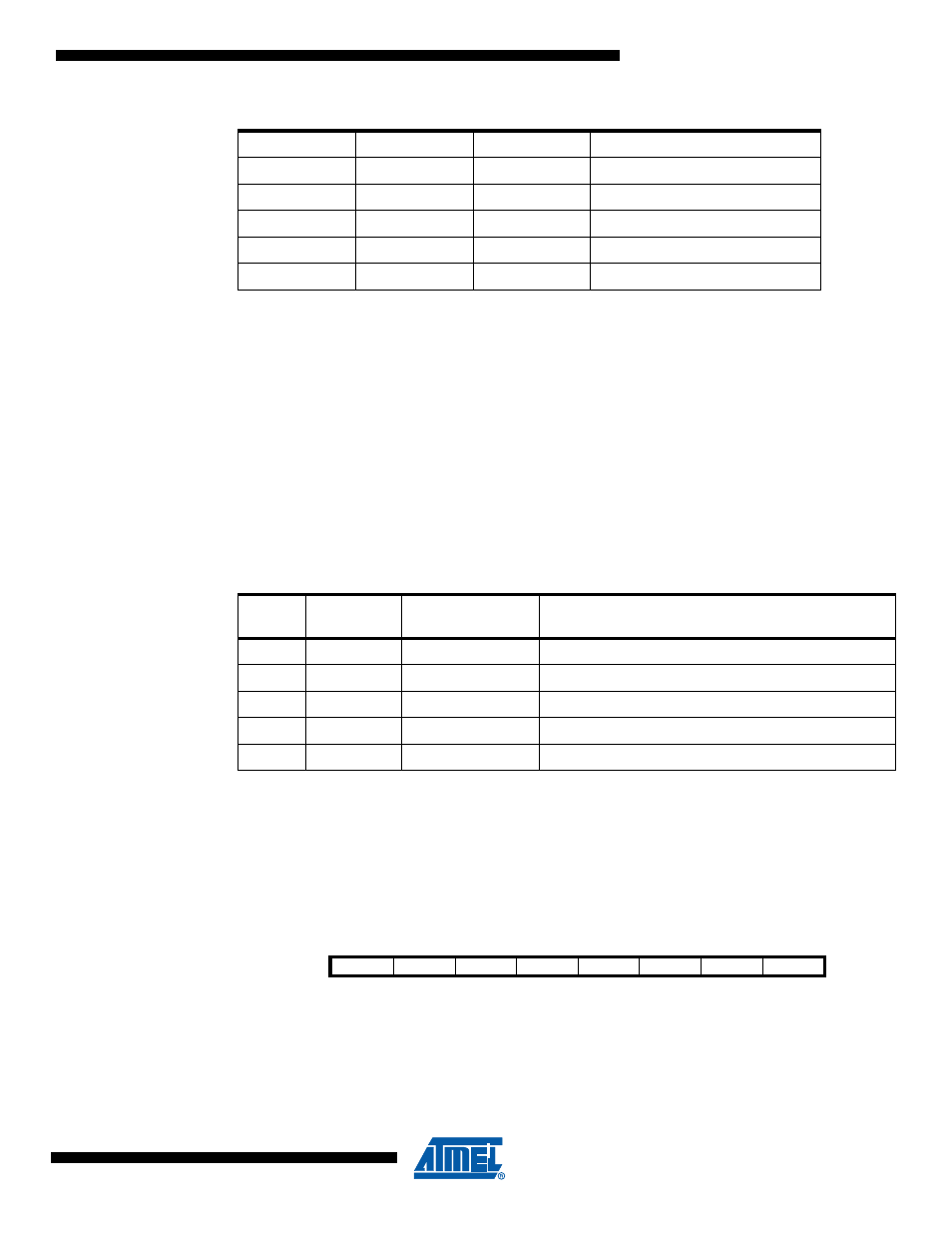
14.15 Interrupts
T h i s s e c t i o n d e s c r i b e s t h e s p e c i f i c s o f t h e i n t e r r u p t h a n d l i n g a s p e r f o r m e d i n
ATmega32/64/M1/C1.
14.15.1
Interrupt Vector
PSC provides 2 interrupt vectors:
•
PSC_End (End of Cycle): When enabled and when a match with POCR_RB occurs
•
PSC_Fault (Fault Event): When enabled and when a PSC input detects a Fault event.
14.15.2
PSC Interrupt Vectors in ATmega32/64/M1/C1
14.16 PSC Register Definition
Registers are explained for PSC module 0. They are identical for module 1 and module 2.
14.16.1
PSC Output Configuration – POC
• Bit 7 – not use
not use
0
1
1
CLK I/O / 256
1
0
0
CLK PLL
1
0
1
CLK PLL / 4
1
1
0
CLK PLL / 32
1
1
1
CLK PLL / 256
Table 14-6.
Output Clock versus Selection and Prescaler
PCLKSELn
PPREn1
PPREn0
CLKPSCn output
Table 14-7.
PSC Interrupt Vectors
Vector
No.
Program
Address
Source
Interrupt Definition
-
-
-
-
5
0x0004
PSC_Fault
PSC Fault event
6
0x0005
PSC_End
PSC End of Cycle
-
-
-
-
-
-
-
-
Bit
7
6
5
4
3
2
1
0
-
-
POEN2B
POEN2A
POEN1B
POEN1A
POEN0B
POEN0A
POC
Read/Write
R/W
R/W
R/W
R/W
R/W
R/W
R/W
R/W
Initial Value
0
0
0
0
0
0
0
0