3 acceptance filter, 5 can data buffers – Rainbow Electronics ATmega64C1 User Manual
Page 179
179
7647A–AVR–02/08
ATmega32/64/M1/C1
16.5.3
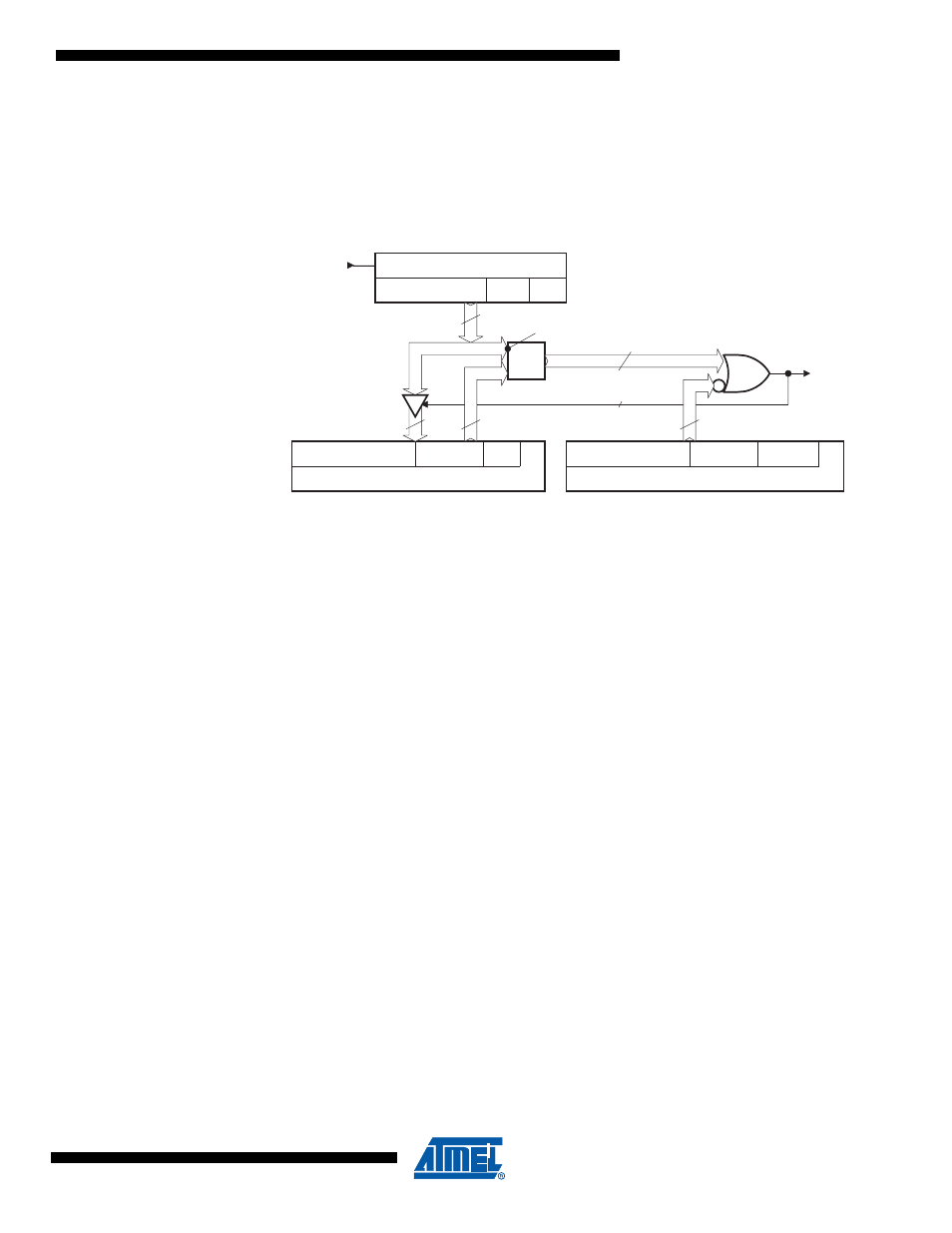
Acceptance Filter
Upon a reception hit (i.e., a good comparison between the ID + RTR + RBn + IDE received and an
IDT+ RTRTAG + RBnTAG + IDE specified while taking the comparison mask into account) the IDT
+ RTRTAG + RBnTAG + IDE received are updated in the MOb (written over the registers).
Figure 16-10. Acceptance Filter Block Diagram
Note:
Examples:
Full filtering: to accept only ID = 0x317 in part A.
- ID MSK = 111 1111 1111
b
- ID TAG = 011 0001 0111
b
Partiel filtering: to accept ID from 0x310 up to 0x317 in part A.
- ID MSK = 111 1111 1000
b
- ID TAG = 011 0001 0xxx
b
No filtering: to accept all ID’s from 0x000 up to 0x7FF in part A.
- ID MSK = 000 0000 0000
b
- ID TAG = xxx xxxx xxxx
b
16.5.4
MOb Page
Every MOb is mapped into a page to save place. The page number is the MOb number. This
page number is set in CANPAGE register. The other numbers are reserved for factory tests.
CANHPMOB register gives the MOb having the highest priority in CANSIT registers. It is format-
ted to provide a direct entry for CANPAGE register. Because CANHPMOB codes CANSIT
registers, it will be only updated if the corresponding enable bits (ENRX, ENTX, ENERR) are
enabled (c.f.
16.5.5
CAN Data Buffers
To preserve register allocation, the CAN data buffer is seen such as a FIFO (with address
pointer accessible) into a MOb selection.This also allows to reduce the risks of un-controlled
accesses.
There is one FIFO per MOb. This FIFO is accessed into a MOb page thanks to the CAN mes-
sage register.
CANIDM Registers (MOb[i])
IDMSK
RTRMSK
IDEMSK
CANIDT Registers & CANCDMOB (MOb[i])
ID & RB
RTRTAG
IDE
internal RxDcan
Rx Shift Register (internal)
ID & RB
RTR
IDE
=
Hit MOb[i]
14(33)
13(31) - RB excluded
RB excluded
13(31)
14(33)
Write
Enable
13(31)
1