7 psc configuration register - pcnf, Table 14-10. psc mode selection – Rainbow Electronics ATmega64C1 User Manual
Page 152
152
7647A–AVR–02/08
ATmega32/64/M1/C1
14.16.5
PSCOutput Compare SB Register – POCRnSBH and POCRnSBL
14.16.6
PSC Output Compare RB Register – POCR_RBH and POCR_RBL
Note : n = 0 to 2 according to module number.
The Output Compare Registers RA, RB, SA and SB contain a 12-bit value that is continuously
compared with the PSC counter value. A match can be used to generate an Output Compare
interrupt, or to generate a waveform output on the associated pin.
The Output Compare Registers are 16bit and 12-bit in size. To ensure that both the high and low
bytes are written simultaneously when the CPU writes to these registers, the access is per-
formed using an 8-bit temporary high byte register (TEMP). This temporary register is shared by
all the other 16-bit registers.
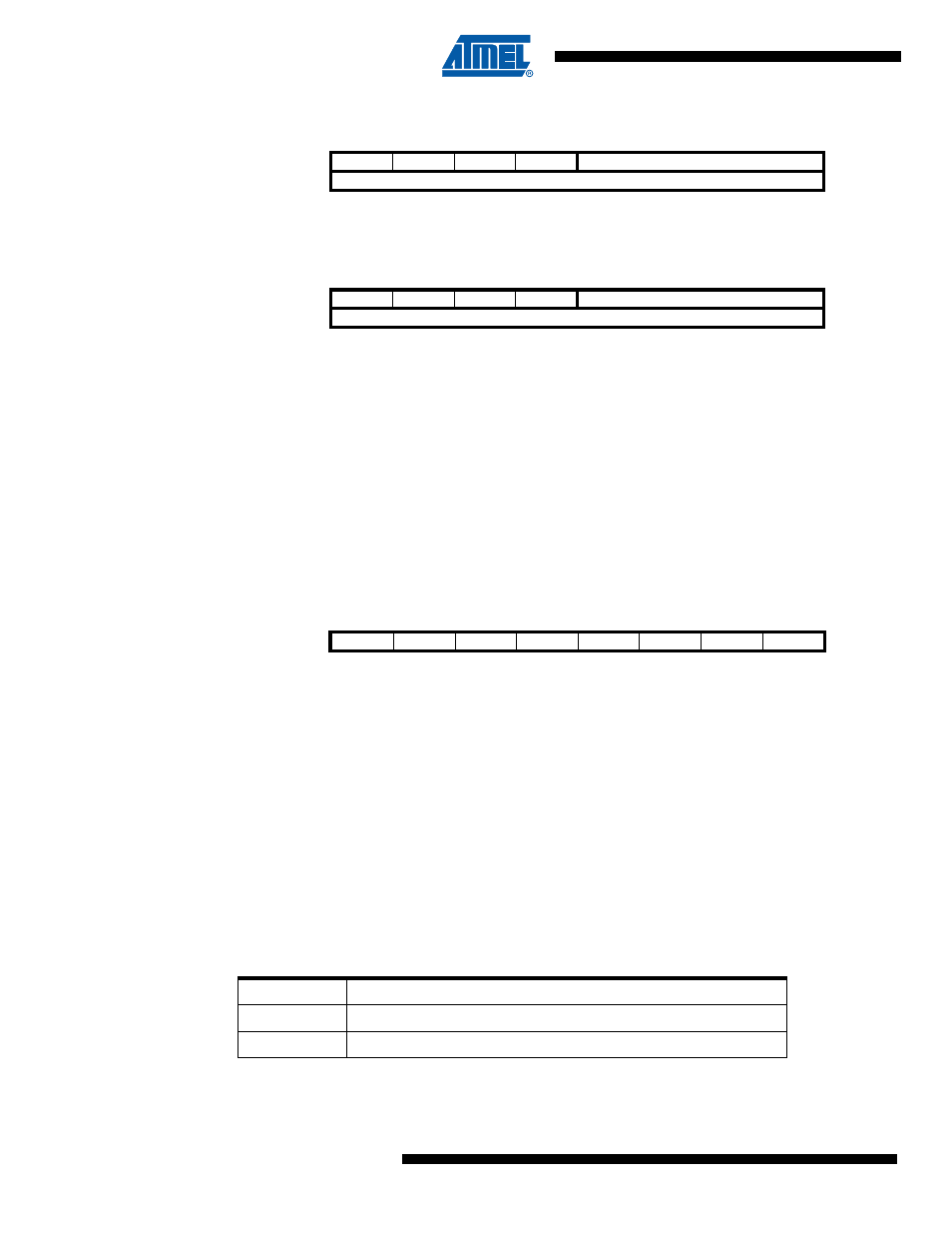
14.16.7
PSC Configuration Register – PCNF
• Bit 7:6 - not use
not use
• Bit 5 – PULOCK: PSC Update Lock
When this bit is set, the Output Compare Registers POCRnRA, POCRnSA, POCRnSB,
POCR_RB and the PSC Output Configuration Registers POC can be written without disturbing
the PSC cycles. The update of the PSC internal registers will be done if the PULOCK bit is
released to zero.
• Bit 4 – PMODE PSC Mode
Select the mode of PSC.
Bit
7
6
5
4
3
2
1
0
–
–
–
–
POCRnSB[11:8]
POCRnSBH
POCRnSB[7:0]
OCRnSBL
Read/Write
R/W
R/W
R/W
R/W
R/W
R/W
R/W
R/W
Initial Value
0
0
0
0
0
0
0
0
Bit
7
6
5
4
3
2
1
0
–
–
–
–
POCRnRB[11:8]
POCR_RBH
POCRnRB[7:0]
POCR_RBL
Read/Write
R/W
R/W
R/W
R/W
R/W
R/W
R/W
R/W
Initial Value
0
0
0
0
0
0
0
0
Bit
7
6
5
4
3
2
1
0
-
-
PULOCK
PMODE
POPB
POPA
-
-
PCNF
Read/Write
R
R
R/W
R/W
R/W
R/W
R
R
Initial Value
0
0
0
0
0
0
0
0
Table 14-10. PSC Mode Selection
PMODE
Description
0
One Ramp Mode (Edge Aligned)
1
Center Aligned Mode